Search filter
Filter
Reset- Installation drawing (887)
- Product data sheet (760)
- Installation instructions (353)
- Tender texts (294)
- 3D model (181)
- Product scale drawing (146)
- Certificate (113)
- Declarations of performance (91)
- Declaration of conformity (71)
- Cable plan (60)
- Wiring diagram (43)
- Product declaration (LEED, DGNB, EPD) (43)
- User manual (30)
- Supplementary sheet (26)
- Flyer/folder (24)
- Product brochure (24)
- Type examination certificate (9)
- T&C / Data Protection (7)
- Software (5)
- Supplier information (4)
- Safety analysis (2)
- Evaluation/comment (2)
- Customer information (1)
3176 results found
Award certificate OL 90 fanlight openers with hand lever and scissor stay gripping and cleaning scissor stay
Der Güteausschuss der Gütegemeinschaft Schlösser und Beschläge e.V. verleiht hiermit aufgrund des vorliegenden Prüfprotokolls gemäß RAL-RG 607/12 dem Based upon the test report according to RAL-RG 607/12 which has been released by the quality assurance commission of the quality assurance association of locks and hardware hereby awards OL 90 Oberlichtöffner mit Handhebel sowie der Fangschere FPS Fensterwerkstoff: Holz Die Prüfergebnisse sind auf andere Fensterwerkstoffe übertragbar. OL 90 Fanlight opener with hand lever and the safety shear FPS, window material: wood. The test results are transferable for other window materials der Mitgliedsfirma the membership company GEZE GmbH, D-71226 Leonberg das von RAL (Deutsches Institut für Gütesicherung und Kennzeichnung e.V.) anerkannte und durch Eintragung beim Deutschen Patentamt als Kollektivmarke geschützte Gütezeichen Schlösser und Beschläge mit der Inschrift „Oberlichtbeschläge“ The RAL-quality label shown below, having been recognized by the German RAL Institute for Quality Assurance and labelling and trademark-legally protected by the registration in the German Patent Agency “Fanlight hardware” Geprüft nach RAL-RG 607/12, Ausgabe … certified according to RAL-RG 607/12, issued … Die Führung des Zeichens setzt die Einhaltung und Überwachung nach dieser Güte- und Prüfbestimmung voraus. Die Kennzeichnung, die Gültigkeit und die wesentlichen Bestandteile des geprüften Produktes sind in dem gleichlautenden Prüfprotokoll Nr. 13-4/99 beschrieben. Permission of using this RAL quality label is based on the surveillance and the quality- and testing instructions of RAL-RG 607/12. The labelling, the validity and the main components of the tested product are specified in the test report no. 13-4/99. D-42551 Velbert, den 12. Juni/ June 2012 -Erstausstellung/ First issue am 23. Juli/ July 2001- Gütegemeinschaft Schlösser und Beschläge e.V. Geschäftsführer
PDF | 513 KB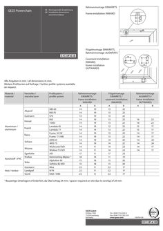
Supplementary sheet installation dimensions Powerchain
DE Montagemaße Empfehlung GB Installation dimensions recommendation Rahmenmontage einwärts Frame installation inward 11 11 B A GEZE Powerchain 28 C 11 26 B A 11 Flügelmontage einwärts, Rahmenmontage auswärts B A 26 Casement installation inward, frame installation outwards 18 … 24 Alle Angaben in mm / all dimensions in mm. Weitere Profilserien auf Anfrage / further profile systems available on request. Material / material Hersteller / manufacturer Aluprof Gutmann Heroal Aluminium / aluminium Hueck Raico Schüco Wicona Kunststoff / PVC EgoKiefer Profine Veka Holz / timber 1) Gutmann Landgraf Oertli Profilsystem / profile system MB-60 MB-70 S70 065 110ES Lambda 65 Lambda 77 Frame+ 65 W Frame+ 75 WB AWS 65 AWS 75 Wicline 65 EVO Wicline 75 EVO AS1 Kömmerling 88plus 1) Alphaline 90 Softline 82 MD Mira IV79 IV68 / IV80 B A 18 26 … K Rahmenmontage EINWÄRTS / frame installation inward A B 14 19 14 19 14 19 14 19 14 19 14 19 14 19 14 19 14 19 14 19 14 19 14 11 14 11 17 11 18 14 15 18 15 18 22 11 22 11 22 11 Flügelmontage EINWÄRTS / casement installation inwards A B 13 22 13 22 13 22 13 22 13 22 13 22 13 22 13 22 13 22 14 22 14 22 14 22 14 22 17 23 11 19 15 20 15 20 22 17 22 17 22 17 24 Rahmenmontage AUSWÄRTS / frame installation outwards A B 16 16 15 15 14 14 14 14 14 14 Bauseitige Unterlagen erforderlich, da Überschlag 24 mm / spacer required on site due to overlap of 24 mm GEZE GmbH P.O.Box 1363 71229 Leonberg Germany Tel.: 0049 7152 203-0 Fax: 0049 7152 203-310 www.geze.com 155754-00 22 22 17 17 17 17 24 24 17 17
PDF | 670 KB
Product declaration EPD Certificate of electrical control centres for smoke and heat extraction system and ventilation systems
Environmental Product Declaration (EPD) Declaration code: M-EPD-SVR-GB-104 Note: This EPD is based on the model EPD Electrical control units and pneumatic valves / alert stations. GEZE GmbH Building components for smoke and heat control systems Electrical control units and pneumatic valves / alert stations for SHEV and ventilation systems Basis: DIN EN ISO 14025 EN15804 Model-EPD Environmental Product Declaration date of issue: … .2019 next Revision: … .2024 www.ift-rosenheim.de/ erstellte-epds Environmental Product Declaration (EPD) Declaration code: M-EPD-SVR-GB-104 Programme operator ift Rosenheim GmbH Theodor-Gietl-Straße 7-9 83026 Rosenheim Practitioner of the LCA LCEE Life Cycle Engineering Experts GmbH Berliner Allee 58 64295 Darmstadt Declaration holder GEZE GmbH Reinhold-Vöster-Straße 21-29 71229 Leonberg Declaration code M-EPD-SVR-GB-104 Designation of the declared product Electrical control units and pneumatic valves / alert stations for SHEV and ventilation systems Scope Basis Smoke and heat exhaust ventilation systems, or their components, which, through their interaction, exhaust smoke and heat from buildings. Smoke and heat control systems. Ventilation systems for maintaining specific air change rates. This model EPD was prepared on the basis of EN ISO 14025:2011 and EN 15804:2012+A1:2013. In addition, the “Allgemeiner Leitfaden zur Erstellung von Typ II Umweltproduktdeklarationen” (General guideline for elaboration of Type III Environmental Product Declarations) applies. The Declaration is based on the PCR Documents “Bauteile für Anlagen zur Rauch- und Wärmefreihaltung” (Building components for smoke and heat control systems) PCR-RW- … :2018 and “PCR Teil A” (Part A) PCR-A- … :2018. Publication date: … .2019 Validity LCA basis Notes on publication Prof. Ulrich Sieberath Director of Institute Date of issue: … .2019 Next revision: … .2024 This verified model Environmental Product Declaration applies solely to the specified products and is valid for all members of the association window automation and smoke axtraction e.V. (VFE). It has a validity of … years from the date of publication in accordance with DIN EN 15804. The LCA was prepared in accordance with EN ISO 14040 and DIN EN ISO 14044. The base data include both data collected the GEZE GmbH production sithe and the generic data derived from the "GaBi 8" database. LCA calculations were based on the "cradle to gate with options" life cycle including all upstream processes (e.g. raw materials extraction, etc.). The "Conditions and Guidance on the Use of ift Test Documents" apply. The declaration holder assumes full liability for the underlying data, certificates and verifications. This document is currently being updated. The date for the next revision has been adjusted to … .2024. Patrick Wortner External Verifier EPD Electrical control units and pneumatic valves / alert stations page … Declaration code: M-EPD-SVR-GB-104 Date of issue: … .2019 Product group: Building components for smoke and heat control systems … General product information product definition This EPD relates to the product group Building components for smoke and heat control systems and applies to the following products of the members of the VFE: … Watt (Power) electrical control unit … piece pneumatic valves / alert station of the company GEZE GmbH The average unit is declared as follows: The directly used material flows were divided by the number of considered products and assigned to the declared unit. All other inputs and outputs in the manufacture were scaled to the declared unit as a whole. The reference period is 2018. Product description Control unit: The unit is equipped with a control module and an electric power supply that ensures continuous operation even in the situation of a power failure. The wires to the release mechanisms are monitored. In addition to that a variety of comfort ventilation functions are available, e.g. automatic, time-limited ventilation or travel restriction in ventilation mode for demand-based everyday ventilation. Pneumatic valve / alert station: Manual or automatic control module for activating pneumatic cylinders with compressed air or CO2. For a detailed product description refer to the manufacturer specifications or the product specifications of the respective offer/quotation. Product manufacture Delivery of purchases parts Delivery of purchased parts Manufacture + assembly Manufacture + assembly Programming + Test run Test run Packing Packing Shipping Shipping Electrical control unit Pneumatic Valve / alert station EPD Electrical control units and pneumatic valves / alert stations page … Declaration code: M-EPD-SVR-GB-104 Date of issue: … .2019 Product group: Building components for smoke and heat control systems Application Smoke and heat exhaust ventilation systems, or their components, which, through their interaction, exhaust smoke and heat from buildings. Smoke and heat control systems. Ventilation systems for maintaining specific air change rates. Management systems The following management systems are held: • Quality management system according to DIN EN ISO 9001:2015 • Energy management system according to DIN EN ISO 50001:2011 • Environmental management system according to DIN EN ISO 14001:2015 Additional information For additional proof of usability or conformity refer to the CE marking and the documents accompanying the product. … Materials used Primary materials The primary materials used can be found in the Life Cycle Assessment (LCA) (see chapter 6). Declarable substances The product contains no substances from the REACH candidate list (declaration dated 14. Marchh 2019). All relevant safety data sheets are available from GEZE GmbH. … Construction process stage Processing recommendations, installation … The instructions for installation, operation, maintenance and disassembly must be noted. Use stage Emissions to the environment There are no known emissions to indoor air, water and soil. There may be VOC emissions. Reference service life (RSL) RSL information to be declared in an EPD covering the use stage shall be provided by the manufacturer. The RSL shall refer to the declared technical and functional performance of the product within a building. It shall be established in accordance with any specific rules given in European product standards and shall take into account ISO 15686-1, -2, -7 and -8. Where European product standards provide guidance on deriving the RSL, such guidance shall have priority. If the reference service life can´t be determined according to ISO 15686, the BBSR table „Nutzungsdauern von Bauteilen zur Lebenszyklusanalyse nach BNB“ can be used. For further information visit www.nachhaltigesbauen.de Relevant for this EPD is: The reference service life (RSL) can be determined for a “cradle to gate – with options” EPD only if alle the modules A1-A3 and B1-B5 are EPD Electrical control units and pneumatic valves / alert stations page … Declaration code: M-EPD-SVR-GB-104 Date of issue: … .2019 Product group: Building components for smoke and heat control systems specified; The service life of Electrical control units and pneumatic valves / alert stations for SHEV and ventilation systems from GEZE GmbH is optionally specified at 25 years according to the manufacturer. The service life depends on the characteristics of the product and the terms of use. The features described in the EPD are applied, in particular the following: • Outdoor conditions: There are no known normal impacts that have a negative effect on the service life. • Indoor conditions: There are no known normal impacts that have a negative effect on the service life. The reference service life is for the features, which are reported in this EPD or the relevant references for this purpose. The RSL does not reflect the actual life time, which is usually determined by the service life and the redevolpement of a building. It represents no statement about service life, guarantee of performance or promise of guarantee. … End of life stage Possible end-of-life stages Electrical control units and pneumatic valves / alert stations for SHEV and ventilation systems are shipped to the central collection points. There they are gennerally taken apart in their individual parts and separated. The end-of-life stage depends on the site where the products are used and is therefore subject to local regulations. Observe the locally applicable regulatory requirements. In this EPD, the modules of the ned-of-life are represented according to the market situation. Certain parts of metals, electro-components, batteries / accumulators and plastic are recycled. Residual fractions are deposited or partly thermally recycled. Disposal methods The average disposal routes were taken into account in the LCA. All life cycle scenarios are detailed in the Annex. EPD Electrical control units and pneumatic valves / alert stations page … Declaration code: M-EPD-SVR-GB-104 Date of issue: … .2019 Product group: Building components for smoke and heat control systems … Life Cycle Assessment (LCA) Environmental product declarations are based on life cycle analyses (LCAs) which use material and energy flows for the calculation and subsequent representation of environmental impacts. As the basis for this, an LCA was prepared for Electrical control units and pneumatic valves / alert stations for SHEV and ventilation systems The LCA was developed in accordance with EN 15804 and the requirements set out by the international standards DIN EN ISO 14040, DIN EN ISO 14044, ISO 21930 and EN ISO 14025. The LCA is representative of the products presented in the declaration and the specified reference period. … Definition of goal and scope Goal The goal of the LCA is to demonstrate the environmental impacts of Electrical control units and pneumatic valves / alert stations for SHEV and ventilation systems. In accordance with EN 15804, the environmental impacts covered by this Environmental Product Declaration are presented for the entire product life cycle in the form of basic information. Apart from these, no other environmental impacts have been specified. Data quality, data availability, and geographical and timerelated system boundaries The specific data originate exclusively from the fiscal year 2018 and results from interviews of various manufacturers. These were recorded f by on-site collection and originate partly from company records and partly from values directly obtained by measurement. The data were verified for validity by the ift Rosenheim. The generic data originates from the "Professional Datenbank" and "Baustoff Datenbank" (professional database and building materials database) from the software "GaBi 8". The last update of both databases was in 2018. Data from before this date originate also from this databases and are not more than … years old. No other generic data were used for the calculation. Data gaps were either filled with comparable data or conservative assumptions, or the data were cut off in compliance with the … % rule. The life cycle was modelled using the sustainability software tool “GaBi 8” for the development of Life Cycle Assessments. Scope / System boundaries The system boundaries refer to the supply of raw materials and purchased parts, the manufacture, the use and the end-of-life stage of Electrical control units and pneumatic valves / alert stations for SHEV and ventilation systems (cradle to gate with options). No additional data from pre-suppliers / subcontractors or other sites were taken into consideration. EPD Electrical control units and pneumatic valves / alert stations page … Declaration code: M-EPD-SVR-GB-104 Date of issue: … .2019 Product group: Building components for smoke and heat control systems Cut-off criteria All company data collected, i.e. all input and output materials used, the thermal energy and the electricity consumption were taken into consideration. The boundaries cover only the production-relevant data. Building sections / parts of facilities that are not relevant to the manufacture of the products were excluded. The transport distances of the pre-products were taken into consideration as a function of 100 per cent of the mass of Electrical control units and pneumatic valves / alert stations for SHEV and ventilation systems. The transport mix is consisted as follows and is derived from the research project "EPDs for transparent components": • Lorry, 26 - 28 t gross weight / … t payload, Euro 6, freight, 85% utilization, 100 km; • Road train, 28 - 34 t gross weight / 22 t payload, Euro 6, 50% utilization, 50 km; • Freight train, electric and diesel-operated, D 60%, E 51% utilization, 50 km; • Sea ship consumption mix, 50 km The criteria for the exclusion of inputs and outputs as set out in EN 15804 are fulfilled. It can be assumed that the total negligible processes per life cycle stage doesn´t exceed … per cent of the mass or the primary energy. This way the total of negligible processes does not exceed … per cent of the energy and mass input. The life cycle calculation also includes material and energy flows that account for less than … per cent. … Inventory analysis Goal All material and energy flows are described below. The processes covered are presented as input and output parameters and refer to the declared / functional units. The models of the unit processes used for the LCA have been documented in a transparent manner. Life cycle stages The Annex shows the entire life cycle of Electrical control units and pneumatic valves / alert stations for SHEV and ventilation systems. Product stage “A1 – A3”, construction stage “A4 – A5”, use stage “B2 – B4, B6, B7”, end-of-life stage “C1 – C4” and benefits and loads beyond the system boundaries “D” are considered. Benefits The below benefits have been defined as per EN 15804: • Benefits from recycling • Benefits from (thermal and electric) incineration Allocation of co-products During the manufacture of Electrical control units and pneumatic valves / alert stations for SHEV and ventilation systems no allocations occur. EPD Electrical control units and pneumatic valves / alert stations page … Declaration code: M-EPD-SVR-GB-104 Date of issue: … .2019 Product group: Building components for smoke and heat control systems Allocations for reuse, recycling and recovery If Electrical control units and pneumatic valves / alert stations for SHEV and ventilation systems are reused / recycled during product stage (rejects), the elements are shredded, as necessary, and then sorted into original pure components. This is done by various process plants such as magnetic separators. The system boundaries for Electrical control units and pneumatic valves / alert stations for SHEV and ventilation systems were set following their disposal, with termination of their waste characteristics. Allocations beyond life cycle boundaries The use of recycled materials in the product stage is based on the current market-specific situation. In parallel to this, a recycling potential was taken into consideration that reflects the economic value of the product after processing (recyclate). The system boundary of the recycled material was set during collection. Secondary material The use of secondary materials in the module A3 was not considered. Secondary material is not used. Inputs The LCA includes the following production-relevant inputs: Energy The electricity mix is based on “Strommix Germany” (German electricity mix). Fuel oil is based on “Heizöl S Deutschland” (Fuel Oil S Germany). A portion of the process heat is used for space heating. This can however not be quantified, hence a “worst case” figure was taken into account for the product. Water The water consumed by the individual process steps for the manufacture of Electrical control units and pneumatic valves / alert stations for SHEV and ventilation systems is 1.7E-4 l per W electrical drive and 2.6E-4 l per mm pneumatic cylinders. The consumption of fresh water specified in Section … originates (among others) from the upstream processes of the pre-products. Raw material / Pre-products: The chart below shows the use of raw materials / pre-products per cent. … 2 … 4 … 6 Electrical control unit … 2 … 4 … 6 Pneumatic valve / Alert station EPD Electrical control units and pneumatic valves / alert stations page … Declaration code: M-EPD-SVR-GB-104 Date of issue: … .2019 Product group: Building components for smoke and heat control systems No. … 2 … 4 … 6 Material Mass in % Control unit 47 <1 <1 <1 46 … Steel Copper Bass Aluminium Plastic Pneumatic valve … 3 … 72 18 - In addition, the electrical drive contains printed circuit boards that are not listed int the diagram due to the surface reference. Operating supplies Operating supplies for Electrical control units and pneumatic valves / alert stations for SHEV and ventilation systems have not been included in the assessment, as their mass is < 1%. Product package The following quantities of product package accumulate: Outputs Nr. Material … 2 … Wood Carton / paper PE-Film Mass in kg Control unit Pneumatic valve 1.5E-4 1.7E-3 1.1E-5 The LCA includes the following production-relevant outputs per m² Electrical control units and pneumatic valves / alert stations for SHEV and ventilation systems: Waste Secondary raw materials were considered in the benefits. See Section … - Impact assessment. Waste water The manufacture of Electrical control units and pneumatic valves / alert stations for SHEV and ventilation systems produces no waste water per W or piece. … Impact assessment Goal Impact assessment covers inputs and outputs. The impact categories applied named below: Impact categories The models for impact assessment were applied as described in EN 15804-A1. The impact categories presented in the EPD are as follows: • Depletion of abiotic resources (fossil fuels); • Depletion of abiotic resources (elements); EPD Electrical control units and pneumatic valves / alert stations page 10 Declaration code: M-EPD-SVR-GB-104 Date of issue: … .2019 Product group: Building components for smoke and heat control systems • • • • • Waste Acidification of soil and water; Ozone depletion; Global warming; Eutrophication; Photochemical ozone creation. The waste generated during the production of … m² Electrical control units and pneumatic valves / alert stations for SHEV and ventilation systems is evaluated and shown separately for each of the three main fractions, namely trade wastes, special wastes and radioactive wastes. Since waste handling is modelled within the system boundaries, the amounts shown refer to the deposited wastes. A portion of the waste indicated is generated during the manufacture of the pre-products. Declaration code: M-EPD-SVR-GB-104 page 11 Date of issue: … .2019 Results per W Electrical control unit Environmental impacts Unit A1-A3 A4 A5 B2 B3 B4 B6 B7 C1 C2 C3 C4 D Global warming potential kg CO2-Äqv. 0,12 3,88E-03 2,71E-03 0,00 0,36 0,12 2,25E-03 0,00 3,38E-04 3,60E-04 6,16E-02 2,14E-03 -4,50E-02 Depletion potential of stratospheric layer kg R11-Äqv. 4,63E-10 1,28E-15 6,84E-16 0,00 4E-19 4,63E-10 9,97E-08 0,00 1,50E-14 1,19E-16 2,74E-12 9,14E-17 -1,58E-10 Acidification potential of soil and water kg SO2-Äqv. 5,9-E04 1,18E-05 5,32E-07 0,00 1,68E-03 5,90-E04 6,42 0,00 9,66E-07 1,09E-06 1,76E-04 4,28E-07 -1,90E-04 kg PO43— Äqv. 5,98E-05 2,88E-06 1,01E-07 0,00 1,25E-04 5,98E-05 0,58 0,00 8,74E-08 2,67E-07 1,59E-05 6,93E-08 -1,51E-06 kg C2H4-Äqv. 4,2E-05 -3,33E-06 3,59E-08 0,00 1,21E-05 4,20E-05 0,41 0,00 6,16E-08 -3,09E-07 1,12E-05 3,71E-08 -1,10E-06 kg Sb-Äqv. 7,18E-05 3,06E-10 5,07E-11 0,00 3,60E-05 7,18E-05 8,59E-04 0,00 1,29E-10 2,84E-11 2,36E-08 3,31E-11 -2,70E-05 MJ 1,52 5,26E-02 6,99E-04 0,00 4,63 1,52 2,40E-04 0,00 3,61E-03 4,88E-03 0,66 8,84E.04 -0,64 Unit A1-A3 A4 A5 B2 B3 B4 B6 B7 C1 C2 C3 C4 D Renewable primary energy as energy carrier MJ 0,25 2,65E-03 1,22E-04 0,00 1,50 0,25 1,34E-04 0,00 2,02E-03 2,46E-04 0,00 0,00 -0,11 Renewable primary energy for material use MJ 0,00 0,00 0,00 0,00 0,00 0,00 0,00 0,00 0,00 0,00 0,00 0,00 0,00 Total use of renewable primary energy MJ 0,25 2,65E-03 1,22E-04 0,00 1,50 0,25 1,34E-04 0,00 2,02E-03 2,46E-04 0,37 1,27E-04 -0,11 Non-renewable primary energy as energy carrier MJ 1,61 5,28E-02 8,10E-04 0,00 6,00 1,61 3,94E-04 0,00 5,92E-03 4,90E-03 0,00 0,00 -0,60 Non-renewable primary energy for material use MJ 0,06 0,00 0,00 0,00 0,00 0,00 0,00 0,00 0,00 0,00 0,00 0,00 0,00 Total use of non-renewable primary energy MJ 1,67 5,28E-02 8,10E-04 0,00 6,00 1,61 3,94E-04 0,00 5,92E-03 4,90E-03 1,08 9,33E-04 -0,60 Use of secondary materials kg 0,00 0,00 0,00 0,00 0,00 0,00 0,00 0,00 0,00 0,00 0,00 0,00 0,00 Use of renewable secondary fuels MJ 0,00 0,00 0,00 0,00 0,00 0,00 0,00 0,00 0,00 0,00 0,00 0,00 0,00 Use of non-renewable secondary fuels MJ 0,00 0,00 0,00 0,00 0,00 0,00 0,00 0,00 0,00 0,00 0,00 0,00 0,00 Use of net fresh water m3 0,11 2,19E-4 9,07E-05 0,00 1,80E-03 0,00 1,02E-04 0,00 1,54E-03 2,03E-05 0,28 6,47E-05 -0,04 Unit A1-A3 A4 A5 B2 B3 B4 B6 B7 C1 C2 C3 C4 D Hazardous waste disposed kg 7,41E-09 0,00 0,00 0,00 0,00 7,41E-09 0,00 0,00 0,00 0,00 0,00 0,00 0,00 Non-hazardous waste disposed (municipal waste) kg 0,56 1,91E-04 1,75E-04 0,00 2,21 0,56 9,68E-03 0,00 1,46E-03 1,77E-05 0,27 3,35E-03 -0,22 Radioactive waste kg 1,52E-05 7,2E-08 4,72E-08 0,00 2,50E-04 1,52E-05 6,13 0,00 9,21E-07 6,68E-09 1,68E-04 1,95E-08 -8,47E-06 Components for re-use kg 0,00 0,00 0,00 0,00 0,00 0,00 0,00 0,00 0,00 0,00 0,00 0,00 0,00 Materials for recycling kg 5,36E-05 0,00 0,00 0,00 0,00 5,36E-05 0,00 0,00 0,00 0,00 0,00 0,00 0,00 Materials for energy recovery kg 5,00E-05 0,00 0,00 0,00 0,00 5,00E-05 0,00 0,00 0,00 0,00 0,00 0,00 0,00 Exported energy (electricity) MJ 0,00 0,00 3,55E-03 0,00 0,00 0,00 0,00 0,00 0,00 0,00 0,00 -3,85E-03 0,00 Exported energy (thermal energy) MJ 0,00 0,00 8,42E-03 0,00 0,00 0,00 0,00 0,00 0,00 0,00 0,00 -9,32E-03 0,00 Eutrophication potential Formation potential of tropospheric ozone Abiotic depletion potential (ADP - elements) Abiotic depletion potential (ADP - fossil resources) Use of ressources Waste categories and output flows Declaration code: M-EPD-SVR-GB-104 page 12 Date of issue: … .2019 Results per piece Pneumatical valve / alert station Environmental impacts Unit A1-A3 A4 A5 B2 B3 B4 B6 B7 C1 C2 C3 C4 D Global warming potential kg CO2-Äqv. 18,70 0,18 2,26 0,00 0,00 18,70 952,00 0,00 2,75E-02 2,93E-02 6,16E-02 0,82 -11,00 Depletion potential of stratospheric layer kg R11-Äqv. 8,03E-08 5,79E-14 4,20E-13 0,00 0,00 8,03E-08 4,23E-08 0,00 1,22E-12 9,66E-15 2,74E-12 1,67E-14 -1,28E-10 Acidification potential of soil and water kg SO2-Äqv. 6,75E-02 7,39E-04 3,71E-04 0,00 0,00 6,75E-02 2,72 0,00 7,86E-05 8,89E-05 1,76E-04 5,66E-05 -3,68E-02 34 Eutrophication potential kg PO -Äqv. 5,56E-03 1,84E-04 7,22E-05 0,00 0,00 5,56E-03 0,25 0,00 7,11E-06 2,18E-05 1,59E-05 1,2E-05 -2,64E-03 Formation potential of tropospheric ozone kg C2H4-Äqv. 4,35E-03 -2,73E-04 2,6E-05 0,00 0,00 4,35E-03 0,17 0,00 5,02E-06 -2,51E-05 1,12E-05 5,78E-06 -2,30E-03 kg Sb-Äqv. 7,56E-04 1,39E-08 3,74E-08 0,00 0,00 7,56E-04 3,64E-04 0,00 1,05E-08 2,31E-09 2,36E-08 6,28E-09 -3,57E-04 MJ 265,00 2,38 0,53 0,00 0,00 265,00 1,02E-04 0,00 0,29 0,40 0,66 0,10 -129,00 Unit A1-A3 A4 A5 B2 B3 B4 B6 B7 C1 C2 C3 C4 D Renewable primary energy as energy carrier MJ 96,90 0,12 9,66E-02 0,00 0,00 96,90 5,69E-03 0,00 0,16 0,02 0,37 2,05E-02 -42,80 Renewable primary energy for material use MJ 0,00 0,00 0,00 0,00 0,00 0,00 0,00 0,00 0,00 0,00 0,00 0,00 0,00 Total use of renewable primary energy MJ 96,90 0,12 9,66E-02 0,00 0,00 96,90 5,69E-03 0,00 0,16 0,02 0,37 2,05E-02 -42,80 Non-renewable primary energy as energy carrier MJ 318,00 318,00 0,61 0,00 0,00 318,00 1,67E-05 0,00 0,48 0,40 1,08 0,11 -160,00 Non-renewable primary energy for material use MJ 8,20 0,00 0,00 0,00 0,00 0,00 0,00 0,00 0,00 0,00 0,00 0,00 0,00 Total use of non-renewable primary energy MJ 326,20 2,39 0,61 0,00 0,00 318,00 1,67E-04 0,00 0,48 0,40 1,08 0,11 -160,00 Use of secondary materials kg 0,00 0,00 0,00 0,00 0,00 0,00 0,00 0,00 0,00 0,00 0,00 0,00 0,00 Use of renewable secondary fuels MJ 0,00 0,00 0,00 0,00 0,00 0,00 0,00 0,00 0,00 0,00 0,00 0,00 0,00 Use of non-renewable secondary fuels MJ 0,00 0,00 0,00 0,00 0,00 0,00 0,00 0,00 0,00 0,00 0,00 0,00 0,00 149,00 9,92E-03 6,66E-02 0,00 0,00 149,00 4,33E-03 0,00 0,13 1,65E-03 0,28 1,15E-02 -86,50 Unit A1-A3 A4 A5 B2 B3 B4 B6 B7 C1 C2 C3 C4 D Hazardous waste disposed kg 2,91E-05 0,00 0,00 0,00 0,00 2,91E-05 0,00 0,00 0,00 0,00 0,00 0,00 0,00 Non-hazardous waste disposed (municipal waste) kg 51,70 1,91 1,75 0,00 2,21 51,70 9,68E-03 0,00 1,46E-03 1,77E-05 0,27 3,35E-03 -0,22 Radioactive waste kg 2,03 7,20E-08 4,72E-08 0,00 2,50 2,03E-02 6,13 0,00 9,21E-07 6,68E-09 1,68E-04 1,95E-08 -8,47E-06 Components for re-use kg 0,00 0,00 0,00 0,00 0,00 0,00 0,00 0,00 0,00 0,00 0,00 0,00 0,00 Materials for recycling kg 0,13 0,00 0,00 0,00 0,00 0,13 0,00 0,00 0,00 0,00 0,00 0,00 0,00 Materials for energy recovery kg 0,14 0,00 0,00 0,00 0,00 0,14 0,00 0,00 0,00 0,00 0,00 0,00 0,00 Exported energy (electricity) MJ 0,00 0,00 2,96 0,00 0,00 0,00 0,00 0,00 0,00 0,00 0,00 -1,52 0,00 Exported energy (thermal energy) MJ 0,00 0,00 7,09 0,00 0,00 0,00 0,00 0,00 0,00 0,00 0,00 -3,67 0,00 Abiotic depletion potential (ADP - elements) Abiotic depletion potential (ADP - fossil resources) Use of ressources Use of net fresh water Waste categories and output flows m … EPD Electrical control units and pneumatic valves / alert stations page 13 Declaration code: M-EPD-SVR-GB-104 Date of issue: … .2019 Product group: Building components for smoke and heat control systems … Interpretation, LCA presentation and critical verification Evaluation Environmental impacts of … W control unit are determinated in almost all category by the e-plantine and accumulator used. The steel and packaging used play a secondary role. Environmental impacts caused by the manufacture and transports are marginal. Environmental impacts of … piece pneumatical valve are dominated in almost all categories by the aluminium used and manufacture. The plastic, e-plantine and packaging used play a underpart. Impacts caused by transports are marginal. In the recycling of electrical control units and pneumatic valves, nearly 40 – 60 % of the environmental impacts that occur during the manufacture can be credited to Scenario D. Compared to the EPD five years ago, the LCA results vary considerably in some extent. These result from the new data collection and the newly defined declared unit. The breakdown of the major environmental impacts is shown in the diagram below. The values obtained from the LCA calculation are suitable for the certification of buildings, as necessary. Diagrams Electrical control unit EPD Electrical control units and pneumatic valves / alert stations page 14 Declaration code: M-EPD-SVR-GB-104 Date of issue: … .2019 Product group: Building components for smoke and heat control systems Pneumatical valves / alert stations Report The LCA underlying this EPD was developed according to the requirements of DIN EN ISO 14040 and DIN EN ISO 14044 as well as EN 15804 and EN ISO 14025. It is not addressed to third parties for confidentiality reasons. It is deposited with the ift Rosenheim. The results and conclusions reported to the target group are complete, correct, without bias and transparent. The results of the study are not designed to be used for comparative statements intended for publication. Critical review The critical review of the LCA and the report took place in the course of verification of the EPD by the external verifier Patrick Wortner, MBA and Eng., Dipl.-Ing. (FH). … General information regarding the EPD Comparability This EPD was prepared in accordance with EN 15804 and is therefore only comparable to those EPDs that that also comply with the requirements set out in EN 15804. Any comparison must refer to the building context and the same boundary conditions of the various life cycle stages. For comparing EPDs of construction products, the rules set out in EN 15804 (Clause … ) apply. The individual results of the products were summarized on the basis of conservative assumptions and differ from the average results. The determination of the product groups and the resulting variation is documented in the report. Communication The communications format of this EPD meets the requirements of EN 15942:2011 and is therefore the basis for B2B communication. Only the nomenclature has been changed according to EN 15804. EPD Electrical control units and pneumatic valves / alert stations page 15 Declaration code: M-EPD-SVR-GB-104 Date of issue: … .2019 Product group: Building components for smoke and heat control systems Verification Verification of the Environmental Product Declaration is documented in accordance with the "Richtlinie zur Erstellung von Typ III Umweltproduktdeklarationen" (Guidance on preparing Type III Environmental Product Declarations) in accordance with the requirements set out in ISO 14025. This Declaration is based on the ift PCR documents “Bauteile für Anlagen zur Rauch- und Wärmefreihaltung” (Building components for smoke and heat control systems) PCR-RW- … :2018 and “PCR Teil A” (Part A) PCR-A- … :2018. The European standard EN 15804 serves as the core PCR a) Independent verification of the Declaration and statement according to EN ISO 14025:2010 internal external Independent third party verifier: b) Patrick Wortner a) Product category rules b) Optional for business-to-business communication, mandatory for business-to-consumer communication (see EN ISO 14025:2010, … ) Revisions of this document No. Date Note … 2 … 4 … .2018 … .2019 … .2024 … .2024 Initial creation External verificaton Date correction Adjustment of date for next revision Practitioner of the LCA Zwick Zwick Brechleiter Brechleiter Verifier/s Wortner Wortner - EPD Control units and pneumatic valves / alert stations page 16 Declaration code: M-EPD-SVR-GB-104 Date of issue: … .2019 Product group: Building components for smoke and heat control systems … Literaturverzeichnis 1. Forschungsvorhaben. EPDs für transparente Bauelemente - Abschlussbericht. Rosenheim : ift Rosenheim GmbH, 2011. SF10. … .7- … /II 3-F20-09-1-067. 2. DIN EN ISO 16000-9:2008-04. Innenraumluftverunreinigungen - Teil 9: Bestimmung der Emissionen von flüchtigen organischen Verbindungen aus Bauprodukten und Einrichtungsgegenständen Emissionsprüfkammer-Verfahren. Berlin : Beuth Verlag GmbH, 2008. 3. DIN ISO 16000-6:2012-11. Innenraumluftverunreinigungen - Teil 6: Bestimmung von VOC in der Innenraumluft und in Prüfkammern, Probenahme auf TENAX TA®, thermische Desorption und Gaschromatografie mit MS/FID. Berlin : Beuth Verlag GmbH, 2012. 4. Klöpffer, W und Grahl, B. Ökobilanzen (LCA). Weinheim : Wiley-VCH-Verlag, 2009. 5. Hütter, A. Verkehr auf einen Blick. Wiesbaden : Statistisches Bundesamt, 2013. 6. Eyerer, P. und Reinhardt, H.-W. Ökologische Bilanzierung von Baustoffen und Gebäuden - Wege zu einer ganzheitlichen Bilanzierung. Basel : Birkhäuser Verlag, 2000. 7. Gefahrstoffverordnung - GefStoffV. Verordnung zum Schutz vor Gefahrstoffen. Berlin : BGBI. I S. 3758, 2017. 8. Chemikalien-Verbotsverordnung ChemVerbotsV. Verordnung über Verbote und Beschränkungen des Inverkehrbringens gefährlicher Stoffe, Zubereitungen und Erzeugnisse nach Chemikaliengesetz. Berlin : BGBI. I S. 1328, 2017. 9. DIN EN ISO 14040:2018-05. Umweltmanagement - Ökobilanz - Grundsätze und Rahmenbedingungen. Berlin : Beuth Verlag GmbH, 2018. 10. DIN EN ISO 14044:2006-10. Umweltmanagement - Ökobilanz Anforderungen und Anleitungen. Berlin : Beuth Verlag GmbH, 2006. 11. EN ISO 14025:2011-10. Umweltkennzeichnungen und -deklarationen Typ III Umweltdecklarationen - Grundsätze und Verfahren. Berlin : Beuth Verlag GmbH, 2011. 12. OENORM S 5200:2009-04-01. Radioaktivität in Baumaterialien. Berlin : Beuth Verlag GmbH, 2009. 13. PCR Teil B - Trennwände. Produktkategorieregeln für Umweltprodukdeklarationen nach EN ISO 14025 und EN 15804. Rosenheim : ift Rosenheim, 2018. 14. PCR Teil B - Systemböden. Produktkategorieregeln für Umweltprodukdeklarationen nach EN ISO 14025 und EN 15804. Rosenheim : ift Rosenheim, 2018. 15. PCR Teil B - Technische Teile. Produktkategorieregeln für Umweltprodukdeklarationen nach EN ISO 14025 und EN 15804. Rosenheim : ift Rosenheim, 2018. 16. PCR Teil B - Bauteile für Anlagen zur Rauch- und Wärmefreihaltung. Produktkategorieregeln für Umweltprodukdeklarationen nach EN ISO 14025 und EN 15804. Rosenheim : ift Rosenheim, 2018. 17. PCR Teil B - Antriebseinheiten für Tore. Produktkategorieregeln für Umweltprodukdeklarationen nach EN ISO 14025 und EN 15804. Rosenheim : ift Rosenheim, 2018. 18. PCR Teil B - Antriebseinheiten für Fenster und Türen. Produktkategorieregeln für Umweltprodukdeklarationen nach EN ISO 14025 und EN 15804. Rosenheim : ift Rosenheim, 2018. 19. PCR Teil B - Baukörperanschluss-/ Abdichtungssystemme. Produktkategorieregeln für Umweltprodukdeklarationen nach EN ISO 14025 und EN 15804. Rosenheim : ift Rosenheim, 2018. 20. PCR Teil B Oberflächenbeschichtungen. Produktkategorieregeln für Umweltprodukdeklarationen nach EN ISO 14025 und EN 15804. Rosenheim : ift Rosenheim, 2018. 21. PCR Teil B - Bewehrungsstahl. Produktkategorieregeln für Umweltprodukdeklarationen nach EN ISO 14025 und EN 15804. Rosenheim : ift Rosenheim, 2018. 22. PCR Teil B - Dichtungsprofile. Produktkategorieregeln für Umweltprodukdeklarationen nach EN ISO 14025 und EN 15804. Rosenheim : ift EPD Control units and pneumatic valves / alert stations page 17 Declaration code: M-EPD-SVR-GB-104 Date of issue: … .2019 Product group: Building components for smoke and heat control systems Rosenheim, 2018. 23. PCR Teil B - Fassaden und Dächer aus Glas und Kunststoff. Produktkategorieregeln für Umweltprodukdeklarationen nach EN ISO 14025 und EN 15804. Rosenheim : ift Rosenheim, 2018. 24. PCR Teil B - Fenster, Flachdachfenster, Lichtkuppeln und Lichtbänder. Produktkategorieregeln für Umweltprodukdeklarationen nach EN ISO 14025 und EN 15804. Rosenheim : ift Rosenheim, 2018. 25. PCR Teil B - Halbzeuge. Produktkategorieregeln für Umweltprodukdeklarationen nach EN ISO 14025 und EN 15804. Rosenheim : ift Rosenheim, 2018. 26. PCR Teil B - Innenliegender und außenliegender Sonnenschutz (auch Verdunklungssysteme). Produktkategorieregeln für Umweltprodukdeklarationen nach EN ISO 14025 und EN 15804. Rosenheim : ift Rosenheim, 2018. 27. PCR Teil B - Metalldecken. Produktkategorieregeln für Umweltprodukdeklarationen nach EN ISO 14025 und EN 15804. Rosenheim : ift Rosenheim, 2018. 28. PCR Teil B - Produkte für den passiven technischen Brandschutz. Produktkategorieregeln für Umweltprodukdeklarationen nach EN ISO 14025 und EN 15804. Rosenheim : ift Rosenheim, 2018. 29. PCR Teil B - Profile für Fenster, Türen und Fassaden. Produktkategorieregeln für Umweltprodukdeklarationen nach EN ISO 14025 und EN 15804. Rosenheim : ift Rosenheim, 2018. 30. PCR Teil B - Schlösser und Beschläge. Produktkategorieregeln für Umweltprodukdeklarationen nach EN ISO 14025 und EN 15804. Rosenheim : ift Rosenheim, 2018. 31. PCR Teil B - Trockenschüttung. Produktkategorieregeln für Umweltprodukdeklarationen nach EN ISO 14025 und EN 15804. Rosenheim : ift Rosenheim, 2018. 32. PCR Teil B - Türen und Tore. Produktkategorieregeln für Umweltprodukdeklarationen nach EN ISO 14025 und EN 15804. Rosenheim : ift Rosenheim, 2018. 33. PCR Teil B - Verladesysteme. Produktkategorieregeln für Umweltprodukdeklarationen nach EN ISO 14025 und EN 15804. Rosenheim : ift Rosenheim, 2018. 34. PCR Teil B - Profile aus Stahlblech. Produktkategorieregeln für Umweltprodukdeklarationen nach EN ISO 14025 und EN 15804. Rosenheim : ift Rosenheim, 2017. 35. PCR Teil B - Flachglas im Bauwesen. Produktkategorieregeln für Umweltprodukdeklarationen nach EN ISO 14025 und EN 15804. Rosenheim : ift Rosenheim, 2016. 36. PCR Teil B - Führungssysteme für Kabel und Leitungen. Produktkategorieregeln für Umweltprodukdeklarationen nach EN ISO 14025 und EN 15804. Rosenheim : ift Rosenheim, 2016. 37. EN 15942:2012-01. Nachhaltigkeit von Bauwerken - Umweltproduktdeklarationen Kommunikationsformate zwischen Unternehmen. Berlin : Beuth Verlag GmbH, 2012. 38. EN 15804:2012+A1:2013. Nachhaltigkeit von Bauwerken - Umweltdeklarationen für Produkte - Regeln für Produktkategorien. Berlin : Beuth Verlag GmbH, 2013. 39. RAL-Gütegemeinschaft Fenster und Haustüren e.V.; ift Insitut für Fenstertechnik. Leitfaden zur Planung und Ausführung der Montage von Fenstern und Haustüren. Frankfurt : RAL-Gütegemeinschaft Fenster und Haustüren e.V., 2014. 40. Bundesministerium für Umwelt, Naturschutz, Bau und Reaktorsicherheit. Leitfaden Nachhaltiges Bauen. Berlin : s.n., 2016. 41. DIN EN 13501-1:2010-01. Klassifizierung von Bauprodukten und Bauarten zu ihrem Brandverhalten - Teil 1: Klassifizierung mit den Ergebnissen aus den Prüfungen zum Brandverhalten von Bauprodukten. Berlin : Beuth Verlag GmbH, 2010. 42. DIN EN ISO 16000 Teil 6, … 11. Innenraumluftverunreinigungen: Bestimmung der Emissionen von flüchtigen organischen Verbindungen aus Bauprodukten und Einrichtungsgegenständen. Berlin : Beuth EPD Control units and pneumatic valves / alert stations page 18 Declaration code: M-EPD-SVR-GB-104 Date of issue: … .2019 Product group: Building components for smoke and heat control systems Verlag GmbH, 2012, 2008, 2006. 43. ISO 21930:2017-07. Hochbau Nachhaltiges Bauen Umweltproduktdeklarationen von Bauprodukten. Berlin : Beuth Verlag, 2017. 44. Bundesimmissionsschutzgesetz BImSchG. Gesetz zum Schutz vor schädlichen Umwelteinwirkungen durch Luftverunreinigungen, Geräusche, Erschütterungen und ähnlichen Vorgängen. Berlin : BGBI. I S. 3830, 2017. 45. Chemikaliengesetz - ChemG. Gesetz zum Schutz vor gefährlichen Stoffen Unterteilt sich in Chemikaliensetz und eine Reihe von Verordnungen; hier relevant: Gesetz zum Schutz vor gefährlichen Stoffen. Berlin : BGBI. I S. 1146, 2017. 46. IKP Universität Stuttgart und PE Europe GmbH. GaBi 8: Software und Datenbank zur Ganzheitlichen Bilanzierung. LeinfeldenEchterdingen : s.n., 2017. 47. DIN EN 16034:2014-12. Fenster, Türen und Tore - Produktnorm, Leistungseigenschaften - Feuer- und/oder Rauchschutzeigenschaften. Berlin : Beuth Verlag GmbH, 2014. 48. prEN 17213:2018-01. Fenster und Türen Umweltproduktdeklarationen Produktkategorieregeln für Fenster und Türen. Berlin : Beuth Verlag GmbH, 2018. 49. DIN EN 14351-2:2019-01. Fenster und Türen - Produktnorm, Leistungseigenschaften - Teil 2: Innentüren ohne Feuerschutzund/oder Rauchdichtheitseigenschaften. Berlin : Beuth Verlag GmbH, 2019. 50. DIN EN 14351-1:2016-12. Fenster und Türen - Produktnorm, Leistungseigenschaften - Teil 1: Fenster und Außentüren ohne Eigenschaften bezüglich Feuerschutz und/oder Rauchdichtheit. Berlin : Beuth Verlag GmbH, 2016. 51. ETAG 010. ETAG 010 - Selbsttragende lichtdurchlässige Dachbausysteme. Brüssel : EOTA, 2004. 52. DIN EN ISO 12457 Teil 1-4. Charakterisierung von Abfällen - Auslaugung; Übereinstimmungsuntersuchung für die Auslaugung von körnigen Abfällen und Schlämmen - Teil 1-4. Berlin : Beuth Verlag GmbH, 2003. 53. ift-Richtlinie NA-01/3. Allgemeiner Leitfaden zur Erstellung von Typ III Umweltproduktdeklarationen. Rosenheim : ift Rosenheim GmbH, 2015. 54. PCR Teil A. Allgemeine Produktkategorieregeln für Umweltprodukdeklarationen nach EN ISO 14025 und EN 15804. Rosenheim : ift Rosenheim, 2018. EPD Control units and pneumatic valves / alert stations page 19 Declaration code: M-EPD-SVR-GB-104 Date of issue: … .2019 Product group: Building components for smoke and heat control systems … Annex Disposal B1 B2 C1 C2 C3 C4 — — D Re-use Recovery Recycling potential B7 Waste management Construction / Installation B6 Transport Transport B5 Deconstruction Manufacture B4 Operational water use Transport B3 Operational energy use A5 Improvement / Modernisation A4 Exchange / Replacement A3 Repair A2 Inspection, maintenance, cleaning A1 Benefits and loads beyond the system boundaries End of life stage Use stage Use Product stage Construction stage Raw material supply Description of life cycle scenarios for Electrical control units and pneumatic valves / alert stations for SHEV and ventilation systems For the calculation of the scenarios a building life time of 50 years was considered (see RSL … Use stage). The scenarios were based on information provided by the manufacturer. The scenarios were furthermore bases on the research project "EPDs for transparent building components" (1). Note: The standard scenarios selected are presented in bold type. They were also used for calculating the indicators in the summary table. Included in the LCA — Not included in the LCA EPD Control units and pneumatic valves / alert stations page 20 Declaration code: M-EPD-SVR-GB-104 Date of issue: … .2019 Product group: Building components for smoke and heat control systems A4 Transport to construction site Control unit No. Usage scenario Description A4.1 Direct delivery to cunstruction site / branch domestically Small vehicle transporter (Euro 0-6 Mix), 95 per cent capacity used, approx. 50 km distance to sites A4.2 Direct delivery to construction site / branch abroad 7,5 t lorry (Euro 0-6 Mix), 95 per cent capacity used, approx. 800 km distance to sites A4 transport to construction site Control unit Environmental impacts unit A4.1 A4.2 Global warming potential kg CO2-Äqv. 6,21E-03 5,15E-03 Depletion potential of stratospheric layer kg R11-Äqv. 2,05E-15 2,15E-15 Acidification potential of soil and water kg SO2-Äqv. 1,88E-05 1,98E-05 Eutrophication potential kg PO43--Äqv. 4,62E-06 4,86E-06 Formation potential of tropospheric ozone kg C2H4-Äqv. -5,33E-06 -7,01E-06 kg Sb-Äqv. 4,90E-10 5,9E-10 Abiotic depletion potential (ADP - fossil resources) MJ 8,43E-02 9,16E-02 Use of ressources unit A4.1 A4.2 Renewable primary energy as energy carrier MJ 4,25E-03 5,12E-03 Renewable primary energy for material use MJ 0,00 0,00 Total use of renewable primary energy MJ 4,25E-03 5,12E-03 Non-renewable primary energy as energy carrier MJ 8,46E-02 9,50E-02 Non-renewable primary energy for material use MJ 0,00 0,00 Total use of non-renewable primary energy MJ 8,46E-02 9,50E-02 Use of secondary materials kg 0,00 0,00 Use of renewable secondary fuels MJ 0,00 0,00 Use of non-renewable secondary fuels MJ 0,00 0,00 Use of net fresh water m3 3,51E-04 3,89E-04 unit A4.1 A4.2 Hazardous waste disposed kg 0,00 0,00 Non-hazardous waste disposed (municipal waste) kg 1,91E-04 2,54E-04 Radioactive waste kg 7,2E-08 9,6E-08 Components for re-use kg 0,00 0,00 Materials for recycling kg 0,00 0,00 Materials for energy recovery kg 0,00 0,00 Exported energy (electricity) MJ 0,00 0,00 Exported energy (thermal energy) MJ 0,00 0,00 Abiotic depletion potential (ADP - elements) Waste categories and output flows EPD Control units and pneumatic valves / alert stations page 21 Declaration code: M-EPD-SVR-GB-104 Date of issue: … .2019 Product group: Building components for smoke and heat control systems A4 Transport to construction site Pneumatic valves / alert stations No. Usage scenario Description A4.1 Direct delivery to cunstruction site / branch domestically Small vehicle transporter (Euro 0-6 Mix), 95 per cent capacity used, approx. 50 km distance to sites A4.2 Direct delivery to construction site / branch abroad 7,5 t lorry (Euro 0-6 Mix), 95 per cent capacity used, approx. 800 km distance to sites A4 transport to construction site Pneumatic valves / alert stations Environmental impacts unit A4.1 A4.2 Global warming potential kg CO2-Äqv. 0,18 0,36 Depletion potential of stratospheric layer kg R11-Äqv. 5,79E-14 8E-14 Acidification potential of soil and water kg SO2-Äqv. 7,39E-04 1,10E-03 Eutrophication potential kg PO43--Äqv. 1,84E-04 3,2,E-04 Formation potential of tropospheric ozone kg C2H4-Äqv. -2,73E-04 -4,13E-04 kg Sb-Äqv. 1,39E-08 2,9E-08 Abiotic depletion potential (ADP - fossil resources) MJ 2,38 4,21 Use of ressources unit A4.1 A4.2 Renewable primary energy as energy carrier MJ 0,12 0,12 Renewable primary energy for material use MJ 0,00 0,00 Total use of renewable primary energy MJ 0,12 0,12 Non-renewable primary energy as energy carrier MJ 2,39 3,90 Non-renewable primary energy for material use MJ 0,00 0,00 Total use of non-renewable primary energy MJ 2,39 3,90 Use of secondary materials kg 0,00 0,00 Use of renewable secondary fuels MJ 0,00 0,00 Use of non-renewable secondary fuels MJ 0,00 0,00 Use of net fresh water m3 9,92E-03 1,60E-02 unit A4.1 A4.2 Hazardous waste disposed kg 0,00 0,00 Non-hazardous waste disposed (municipal waste) kg 1,91E-04 0,0003 Radioactive waste kg 7,2E-08 2,7E-07 Components for re-use kg 0,00 0,00 Materials for recycling kg 0,00 0,00 Materials for energy recovery kg 0,00 0,00 Exported energy (electricity) MJ 0,00 0,00 Exported energy (thermal energy) MJ 0,00 0,00 Abiotic depletion potential (ADP - elements) Waste categories and output flows EPD Control units and pneumatic valves / alert stations page 22 Declaration code: M-EPD-SVR-GB-104 Date of issue: … .2019 Product group: Building components for smoke and heat control systems A5 Construction / Installation No. A5 Usage scenario Description manual Electrical control units and pneumatic valves / alert stations for SHEV and ventilation systems are installed without the need of additional lifting equipment means accoring to the manufacturer In case of deviating consumption during the construction or installation of the products forms part of the site management and is covered at the building level. Operating supplies, the use of water, losses of material and waste materials as well as transport distances during construction / installation can be neglected. It is assumed that the packaging material is fed to the waste treatment in the module "construction / installation". Waste is thermally recycled. Credits from A5 are shown in module D. Credits from waste incineration plant: electricity replaces electricity mix EU 28; Thermal energy replaces thermal energy from natural gas (EU 28). The transport to the treatment plants is not taken into account. Since this is the only scenario, the results are shown in the summary table. EPD Control units and pneumatic valves / alert stations page 23 Declaration code: M-EPD-SVR-GB-104 Date of issue: … .2019 Product group: Building components for smoke and heat control systems B1 use of the installed product (not considered) See chapter … Use stage - Emissions to the environment. Emissions can’t be quantified. B2 Inspection, maintenance, cleaning B2.1 Cleaning There is no cleaning required. Operating supplies, the use of energy / water, losses of material and waste materials as well as transport distances during cleaning can be neglected. Since this is the only scenario, the results are shown in the summary table. B2.2 Inspection, maintenance No. Usage scenario Description B2.2 normal load Annual functional testing, visual inspection and possibly mending Operating supplies, the use of energy / water, losses of material and waste materials as well as transport distances during maintenance can be neglected. Since this is the only scenario, the results are shown in the summary table. B3 Repair No. Usage scenario Description Control unit: Repeated replacement*: accumulators (12,5 times) B3 Normal load and high load Pneumatic valves / alert stations: No replacement* required * Assumptions for the assessment of possible environmental impacts; Statements do not constitute a promise of guarantee or warranty of any characteristics Current information can be found in the respective instructions for installation, operation, maintenance and disassembly for Electrical control units and pneumatic valves / alert stations for SHEV and ventilation systems. The service life of the Electrical control units and pneumatic valves / alert stations for SHEV and ventilation systems from the GEZE GmbH is declared with 25 years. For the scenario B3 the respective components of the parts are accounted, if their service life is less than the given period of 50 years. Operating supplies, the use of energy / water, losses of material and waste materials as well as transport distances during repair can be neglected. Since this is the only scenario, the results are shown in the summary table. EPD Control units and pneumatic valves / alert stations page 24 Declaration code: M-EPD-SVR-GB-104 Date of issue: … .2019 Product group: Building components for smoke and heat control systems B4 Exchange / Replacement No. Usage scenario Description B4 Normal load and high load 1-time replacement* in 50 years: complete replacement * Assumptions for the assessment of possible environmental impacts; Statements do not constitute a promise of guarantee or warranty of any characteristics In this EPD, only informative information is given to allow consideration at building level. With a service life of 25 years and the scheduled building service life of 50 years, 1-time replacements are planned. Current information can be found in the respective instructions for installation, operation, maintenance and disassembly for Electrical control units and pneumatic valves / alert stations for SHEV and ventilation systems. In the chosen scenario, environmental impacts from the manufacture occur. Operating supplies, the use of energy / water, losses of material and waste materials as well as transport distances during exchange / replacement are taken into account. Since this is the only scenario, the results are shown in the summary table. B6 Operational energy use No. B6 Usage scenario power-operated, normal load Description Control unit: 5,060 kWh/50a electricity (domestic current 200 Ah at 24 V; annual battery charge over 24 h 1,5 Ah at 24 V – … ,60 kWh per control unit) … ,60 kWh/50a electricity * Frequencies, service life, number of users, cycles, etc. There are no transport efforts during the energy use in the building. Operating supplies, the use of water, waste materials and other scenarios can be neglected. Since this is the only scenario, the results are shown in the summary table. B7 Operational water use (not relevant) No water consumption when used as intended. Water consumption for cleaning is specified in module B2.1. There are no transport efforts during the water use in the building. Operating supplies, the use of energy, waste materials and other scenarios can be neglected. Since this is the only scenario, the results are shown in the summary table. EPD Control units and pneumatic valves / alert stations page 25 Declaration code: M-EPD-SVR-GB-104 Date of issue: … .2019 Product group: Building components for smoke and heat control systems C1 Deconstruction No. Usage scenario Description 99 % dismantling; C1 Deconstruction Further dismantling rates possible, appropriately substantiates. In case of deviating consumption the removal of the products forms part of the site management and is covered at the building level. Since this is the only scenario, the results are shown in the summary table. C2 Transport No. Usage scenario Description Transport to the collecting point using a small vehicle transporter (Euro 0-6 Mix), 80 % capacity used, 50 km distance Since this is the only scenario, the results are shown in the summary table. C2 Transport C3 Waste management No. C3 Usage scenario Disposal Description Share for the return of materials: • Steel 98% in melting (UBA, “End-of-life vehicles recycling and vehicle disposition“, 2017) • Aluminium 95% in melting (GDA, „Recycling from the beginning“, 2018) • Other metals 97% in melting (UBA, “ End-of-life vehicles recycling and vehicle disposition“, 2017) • Plastic materials 66% thermal recycling in WtE facilities (Future Building, volume 6, 2017) • Plastic materials 34% mechanically recycled (Future Building, volume 6, 2017) • Batteries / Accumulators 84 % (UBA, “Used batteries“, 2018) • Electrical components 87% (on the basis of used electronic equipment 87%; UBA, „Analysis of the data collection according to ElektroG and UStatG for the reporting year 2016 in preparation of the EU reporting obligations“, 2018) • Rest in landfill sites The below table presents the disposal processes and their percentage by mass/weight. The calculation is based on the above mentioned shares in per cent related to the declared unit of the product system. EPD Control units and pneumatic valves / alert stations page 26 Declaration code: M-EPD-SVR-GB-104 Date of issue: … .2019 Product group: Building components for smoke and heat control systems C3 disposal Unit Control unit Pneumatic valve Collection process, collected separately kg 4,46E-02 2,21 Collection process, collected as mixed construction waste kg 0,00 0,00 Recovery system, for re-use kg 0,00 0,00 Recovery system, for recycling kg 3,40E-02 1,76 Recovery system, for energy recovery kg 1,37E-04 0,26 Disposal kg 3,35E-03 7,53E-02 Since this is the only scenario, the results are shown in the overall table. C4 Disposal No. Usage scenario Description C4 Disposal The non-measurable quantities and losses of the reuse/recycling chain (C1 and C3) are modelled as “disposed”. The consumption of scenario C4 results from physical pre-treatment, waste recycling and operating of the disposal site. The benefits obtained here from the substitution of primary material production are allocated to module D, e.g. electricity and heat from waste incineration. Since this is the only scenario, the results are shown in the overall table. EPD Control units and pneumatic valves / alert stations page 27 Declaration code: M-EPD-SVR-GB-104 Date of issue: … .2019 Product group: Building components for smoke and heat control systems D Benefits and loads beyond the system boundaries No. Usage scenario Description Aluminium recyclate from C3 excluding the recyclate used in A3 replaces 60 % of aluminium compound; Steel scrap from C3 excluding the recyclate used in A3 replaces 60 % of steel; Copper scrap from C3 excluding the recyclate used in A3 replaces 60 % of copper-mix; Brass scrap from C3 excluding the recyclate used in A3 replaces 60 % of brass; D Recycling potential Plastic recyclate from C3 excluding the recyclate used in A3 replaces 60 % of plastic profil; Printed circuit board recyclate from C3 excluding the recyclate used in A3 replaces 60 % of printed circuit board; Accumulator scrap from C3 excluding the recyclate used in A3 replaces 60 % of lithium-iron phosphate-battery; Credits from WtE facility: Electricity replaces EU-28 electricity mix; thermal energy replaces thermal energy out of EU-28 natural gas The values in module D results from both, the recycling of the packaging material in module A5 and the deconstruction at the end of the service life. Since this is the only scenario, the results are shown in the overall table. Imprint Practitioner of the LCA LCEE Life Cycle Engineering Experts GmbH Berliner Allee 58 64295 Darmstadt Programme operator ift Rosenheim GmbH Theodor-Gietl-Str. 7-9 83026 Rosenheim Phone: … 80 31/261-0 Fax: … 80 31/261 290 E-Mail: info@ift-rosenheim.de www.ift-rosenheim.de Declaration holder GEZE GmbH Reinhold-Vöster-Straße 21-29 71229 Leonberg Notes This EPD is mainly based on the work and findings of the Institut für Fenstertechnik e.V., Rosenheim (ift Rosenheim) and specifically on the ift-Richtlinie NA-01/3 Allgemeiner Leitfaden zur Erstellung von Typ III Umweltproduktdeklarationen. (Guideline NA-01/3 - Guidance on preparing Type III Environmental Product Declarations). The publication and all of its parts are protected by copyright. Any utilisation outside the confined limits of the copyright provisions is not permitted without the consent of the publishers and is punishable. In particular, this applies to any form of reproduction, translations, storage on microfilm and the storage and processing in electronic systems. Layout ift Rosenheim GmbH - 2015 Photographs (front page) GEZE GmbH © ift Rosenheim, 2019 ift Rosenheim GmbH Theodor-Gietl-Str. 7-9 83026 Rosenheim phone: +49 (0) 80 31/261-0 fax: +49 (0) 80 31/261-290 email: info@ift-rosenheim.de www.ift-rosenheim.de
PDF | 527 KB
Operating and code number keypad Toplock CTS V, CTS BV CTI, CTI B
Operating and Installation Instructions Code Number Keypad Toplock CTS V, CTS BV Keypad with separate evaluating processor unit CTI, CTI B With relay which is integrated in the keypad GEZE GmbH Reinhold-Vöster-Straße 21-29, 71229 Leonberg Phone +49 7152-203-0, Fax +49 7152-203-310 Material no. 129510 Number of rev. 00, Drawing no. 21207-9-0963 Subject to change Description of function The code number keypads are code switching devices which accept up to … different open codes. Each code activates the same potential-free relay output. Via the keypad, up to … code numbers, each a maximum of … digits, are entered with a master code. Once the data has been entered, it will remain stored, even in the case of a power failure. Subsequent to entering the valid open code and pressing the key with the bell symbol, the green LED lights up on the keypad and the relay is activated for approx. … seconds. If the red LED lights up during the code entry an incorrect code has been entered. The red LED goes out after a few seconds. Only then can a new code be entered. If an incorrect code has been entered … consecutive times, the keypad blocks for one minute. CTI, CTI B The device only consists of the keypad. CTS V, CTS BV The device consists of … parts: The keypad and the decoder. The keypad and the decoder are in sync as a pair with one key number. Only keypads and decoders with the same key number can work together. Programming the Devices … Programming a new open code … Press the key “P”. The red LED starts to blink. … Enter the valid master code (see also “Master Code Factory Setting”). … Press the key with the bell symbol. The green LED starts to blink, the red one goes out. (If the red LED is continuously lit up or continues to blink and the green LED does not blink, the entered master code was incorrect. Wait until no LED is lit up and try again.) … Enter the new open code … Enter the number of the storage location (1 – 5) where you want to store the open code. … Press the key with the bell symbol. The green LED goes out and the new open code is now saved under the selected number. Important! Since the number of digits of the open code which is saved under storage location no. … defines the number of valid digits of the open codes which are saved under the storage locations no. … – 5, it must be entered first. The number of digits of the open code which is saved under storage location no. … must be the same for the other open codes. Example: You want to save open code 4711 under the storage location no. 2: Enter the digit sequence: 4711 … If an open code which has been saved under a certain storage location is to be made invalid the corresponding storage location must be overwritten with the new open code. … Programming a new master code … Press the key “P”. The red LED starts to blink. … Enter the valid master code (see also “Master Code Factory Setting”). … Press the key with the bell symbol. The green LED starts to blink, the red LED goes out. If the red LED is continuously lit up or continues to blink and the green LED does not blink the entered master code was incorrect. Wait until no LED is illuminated and try again. … Press the key “P”. The red and the green LED blink. … Enter the new master code … Press the key with the bell symbol. The red and the green LEDs go out and the new master code has been saved. … Programming the Key Number (only for CTS V, CTS BV) The key number can be found in the decoder. … Press the key “P”. The red LED starts to blink. … Enter the valid master code (see also “Master Code Factory Setting”). … Press the key with the bell symbol. The green LED starts to blink, the red LED goes out. If the red LED is continuously lit up or continues to blink and the green LED does not blink the entered master code was incorrect. Wait until no LED is lit up and try again. … Press the key “P”. The red and the green LED blink. … Press the key “P”. The green LED goes out and only the red LED is still blinking. … Enter the 5-digit key number (zeros which are placed in front must also be entered). … Press the key with the bell symbol. The red LED goes out and the key number is now saved. … Reset to Factory Setting … Interrupt operating voltage. … .1 Hold a magnet against key … of the square keypad or key … of the long keypad and reconnect the operating voltage at the same time. The red LED lights up and the green LED blinks briefly. As a result, CTS V, CTS BV has been reset to the factory setting. Important! At the time of switching-on, the magnet must be on the keypad. If the magnet is held against the keypad when the operating voltage is still on only the red LED lights up, but the keypad is not reset. This way, you can also find the correct position for the magnet. CTI, CTI B: Attention! During reset, all programmed open codes and the master code are cleared. After the reset, the factory setting applies. CTS V, CTS BV: First of all, the key number must be programmed to guarantee the function of the keypad with the decoder. Only then, the open codes and the master code are to be reprogrammed. For security reasons, it is very important to change the factory setting again. Factory setting master code: 11111 Factory setting open code: 1234 … Pin Assignment: CTS V, CTS BV Evaluating processor unit Keypad Attention!!! Disconnect the device from the power for any installation work … Pin Assignment: CTI CTI B Relay Relay Attention!!! Disconnect the devices from the power for any installation work. GEZE GmbH P.O. Box 1363 71226 Leonberg Germany GEZE GmbH Reinhold-Vöster-Str. 21-29 71229 Leonberg Germany Tel. +49 (0)71 52-203-0 Fax +49 (0)71 52-203-310 GEZE Online: www.geze.com GEZE Branches Germany GEZE GmbH Niederlassung Nord/Ost Bühringstr.8 13086 Berlin (Weissensee) Tel. +49(0)30-47 89 90-0 Fax. +49(0)30-47 89 90-17 E-Mail: berlin.de@geze.com GEZE GmbH Niederlassung West Nordsternstraße 65 45329 Essen Tel. +49(0)201-830 82-0 Fax. +49(0)201-830 82-20 E-Mail: essen.de@geze.com GEZE GmbH Niederlassung Mitte Adenauerallee … 61440 Oberursel (b. Frankfurt) Tel. +49(0)61 71-6 36 10-0 Fax. +49(0)61 71-6 36 10-1 E-Mail: frankfurt.de@geze.com GEZE GmbH Niederlassung Süd Reinhold-Vöster-Straße 21-29 71229 Leonberg Tel. +49(0)7152-203-594 Fax. +49(0)7152-203-438 E-Mail: leonberg.de@geze.com Subsidiaries Germany GEZE Sonderkonstruktionen GmbH Planken … 97944 Boxberg-Schweigern Tel. +49(0)7930-92 94-0 Fax. +49(0)7930-92 94-10 E-Mail: sk.de@geze.com GEZE SERVICE GmbH Reinhold-Vöster-Str.25 71229 Leonberg Tel. +49(0)7152-92 33-0 Fax. +49(0)7152-92 33-60 E-Mail: info@geze-service.com Asia Europe GEZE Industries (Tianjin) Co., Ltd. Shuangchenzhong Road Beichen Economic Development Area (BEDA) Tianjin 300400, P.R. China Tel. +86 (0) 22-26 97 39 95-0 Fax. +86 (0) 22-26 97 27 02 E-Mail: sales-info@geze.com.cn France GEZE France S.A.R.L ZAC de l’Orme Rond RN 19 77170 Servon Tel. +33 (0) … 60 62 60 70 Fax. +33 (0) … 60 62 60 71 E-Mail: france.fr@geze.com GEZE Industries (Tianjin) Co., Ltd. Branch Office Shanghai Room 3010 Tower 2, Grand Gateway No. … HongQiao Road, XuHui District 200030 Shanghai, P.R. China Tel. +86 (0) 21 64475908 Fax. +86 (0) 21 64472007 E-Mail: gezesh@geze.com.cn Great Britain GEZE Industries (Tianjin) Co., Ltd. Branch Office Guangzhou Room 17C3 Everbright Bank Building, No.689, Tian He Bei Road 510630 Guangzhou, P.R. China Tel. +86 (0) 20 3873842 Fax. +86 (0) 20 38731834 E-Mail: gezegz@geze.com.cn GEZE Industries (Tianjin) Co., Ltd. Branch Office Beijing No. 6-32 Building Jili Avenue Daxing District 100076 Beijing, P.R. China Tel. +86 (0) 10 87965152 Tel. +86 (0) 10 87975178 Fax. +86 (0) 10 87971476 E-Mail: gezebj@geze.com.cn Italy GEZE Italia Srl Via Giotto … 20040 Cambiago (MI) Tel. +39 (0) 02 95 06 95-11 Fax. +39 (0) 02 95 06 95-33 E-Mail: italia.it@geze.it DCLSA Distributors (Pty) Ltd. 1027 Richards Drive, Midrand P.O. Box 7934, Midrand 1685 South Africa Tel. ++27 11 3158286 Fax. ++27 11 31558261 E-Mail: info@dclsa.co.za Middle East U.A.E. GEZE Middle East P.O. Box 17903 Jebel Ali Free Zone Dubai Tel. +971 (0) … 88 33 112 Fax. +971 (0) … 88 33 240 E-Mail: geze@emirates.net.ae Switzerland GEZE Schweiz AG Bodenackerstr. 79 4657 Dulliken Tel. +41 (0) 62-285 54 00 Fax. +41 (0) 62-285 54 01 E-Mail: schweiz.ch@geze.com Spain / Portugal GEZE Iberia S.R.L. Pol.Ind. El Pla C/Comerc, 2-22, Nave 12 08980 Sant Feliu de Llobregat (Barcelona) Tel. +34 (0) … 02 19 40 36 Fax. +34 (0) … 02 19 40 35 E-Mail: info@geze.es Scandinavia GEZE Engineering Roma Srl Via Lucrezia Romana 91 00178 Roma Tel. +39 (0) 06 72 65 31 … Fax. +39 (0) 06 72 65 31 36 E-Mail: roma@geze.biz Benelux GEZE Benelux B.V. Industrieterrein Kapelbeemd Leemkuil … 5626 EA Eindhoven Tel. +31 (0) 40 26 29 08 … Fax. +31 (0) 40 26 29 08 … E-Mail: benelux.nl@geze.com South Africa GEZE SERVICE GmbH Niederlassung Berlin Bühringstr.8 13086 Berlin (Weissensee) Tel. +49(0)30-47 02 17-30 Fax. +49(0)30-47 02 17-33 Yourattentionisdrawntothe “productliabilitylaw“definedliabilityto themanu-facturerforhisproducts whicharecon-tainedinthemain catalogue(productinformation,usage, misuses,productactivity,product maintenance,thedutytoinformandthe dutytoinstruct).Noncompliancewith theseconditionsre-lievesthe manufacturerfromanyliability. GEZE UK Ltd. Blenheim Way Fradley Park Lichfield Staffordshire WS13 8SY Tel. +44 (0) 15 43 44 30 00 Fax. +44 (0) 15 43-44 30 01 E-Mail: info@geze-uk.com Poland GEZE Polska Sp. z o.o. Ul. Annopol 21 03-236 Warszawa Tel. +48 (0) 22 440 44 40 Fax. +48 (0) 22 440 44 00 E-Mail: geze@geze.pl Austria GEZE Austria GmbH Mayrwiesstraße 12 5300 Hallwang b. Salzburg Tel. +43 (0) 662 66 31 42 Fax. +43 (0) 662 66 31 42-15 E-Mail: austria.at@geze.com Sweden GEZE Scandinavia AB Mallslingan 10 Box 7060 18711 Täby Tel. +46 (0) 8-732 34-00 Fax. +46 (0) 8-732 34-99 E-Mail: sverige.se@geze.com Norway GEZE Scandinavia AB avd. Norge Postboks 63 2081 Eidsvoll Tel. +47 (0) 639 572 00 Fax. +47 (0) 639 571 73 E-Mail: norge.se@geze.com Finland GEZE Finland Branch office of GEZE Scandinavia AB Postbox 20 Herralantie 824 15871 Hollola Tel. +358 (0) 10-400 5100 Fax. +358 (0) 10-400 5120 E-Mail: finland.se@geze.com Denmark GEZE Denmark Branch office of GEZE Scandinavia AB Høje Taastrup Boulevard 53 DK - 2630 Taastrup Tel. +45 46-32 33 24 Fax. +45 46-32 33 26 E-Mail: danmark.se@geze.com GEZE Representative: Id. No. 129510 Modification level 00 • Drawing No.. 21207-9-0963 • Printed in Germany • Subject to change without notice The hallmark DIN ISO 9001 of our enterprise
PDF | 311 KB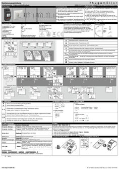
Program timer SC28.21 pro
Bedienungsanleitung D Schaltcomputer / Elektronische Schaltuhr müller SC 18.x0 easy / SC 28.x1 pro4 1. Sicherheitshinweise … Kanal … Kanal Anschlussbilder 3. Technische Daten Anschlussspannung Kontaktwerkstoff (115V / 230V) Kontaktwerkstoff (12V / 24V) Schutzart Umgebungstemperatur Wirkungsweise Verschmutzungsgrad Bemessungsstoßspannung Standard CFL, LED Siehe Gerät AgSnO2 AgNi IP 20 nach DIN EN 60529 -30°…+55° … BSTU … 4 kV DIN EN 60730-1/DIN EN 60730-2-7 Geeignet für moderne Leuchtmittel paladin 170 4x0 easy / 172 4x1 pro4 / 173 110 easy 2. Erstinbetriebnahme ! Einbau und Montage dürfen nur von einer Elektrofachkraft durchgeführt werden! Anderenfalls besteht Brandgefahr oder die Gefahr eines elektrischen Schlages! ! Nur an die auf dem Typenschild angegebene Spannung und Frequenz anschließen! ! Bei Eingriffen oder Änderungen an der Schaltuhr erlischt die Garantie! ! Die Schaltuhr ist so zu installieren, dass außergewöhnlich hohe Störstrahlung die Funktion nicht beeinträchtigen kann! Schaltuhr wird im Power-Fail-Modus ausgeliefert. Das Display ist Die aus. Drücken Sie die / Taste. Die Displayanzeige erscheint. Schaltuhr ist mit dem aktuellen Datum, der Uhrzeit und der Die europäischen Sommerzeitregel voreingestellt. Sie die gewünschte Sprache mit den -Tasten ein und Stellen bestätigen Sie mit . (Hinweis: Mit der -Taste können Sie jederzeit einen Schritt zurück) Uhrzeit und Sommerzeitregel falls nötig mit den Datum, einstellen und jeweils mit bestätigen. 4. Service 5. Bestimmungsgemäße Verwendung 6. Batterie Hugo Müller GmbH & Co KG Karlstraße 90 DE-78054 VS-Schwenningen +49 7720 80836 www.hugo-mueller.de Das Gerät ist zur Verwendung für folgende Aufgaben vorgesehen: Beleuchtungen im privaten und gewerblichen Bereich, Straßen- und Schaufensterbeleuchtung, Steuerung von Lüftungen, Motoren, Pumpen, Anlagen und Anwesenheitssimulation etc.. Das Gerät ist ausschließlich zum Einsatz in trockenen Räumen geeignet. Das Gerät ist nicht geeignet für sicherheitsrelevante Aufgaben, wie z.B. Fluchttüren, Brandschutzeinrichtungen etc. Verteilereinbau-Produkt: 7. Funktionsübersicht -Tasten 8. Symbolerklärung Kanal eingeschaltet / Programmierung EIN Kanal ausgeschaltet / Programmierung AUS erm Für das aktuelle Datum ist eine Ferien- / Datums-Schaltung aktiv. Aktueller Schaltzustand beruht auf einer programmierten Standardschaltzeit. erm I Akt. Schaltzustand beruht auf manueller Umschaltung des Programms und wird durch das gespeicherte Programm bei der nächsten Schaltzeit geändert. Akt. Schaltzustand beruht auf manueller Umschaltung und bleibt permanent erhalten, bis manuell zurückgesetzt wird. Wochentage Montag ... Sonntag; im Programmier-Modus zeigen Unterstriche an, welche Wochentage aktiviert sind. Aktueller Schaltzustand beruht auf einer Impuls-Schalzeit Schaltuhr ist über PIN gesperrt; PIN-Eingabe erforderlich. 9. Schaltzeit programmieren OK OK OK OK OK OK **Bei … KanalAusführung OK OK OK OK Automatik Modus erm 10. Tastenfunktion 11. Permanent / Zusatz-Schaltzeiten 1. Wechsel vom Automatik-Modus in den Eingabe-Modus. 2. Zurück-Funktion (Eine Ebene zurück). 1. Eingabe-Modus: Auswahlmöglichkeit zwischen verschiedenen Optionen . 2. Eingabe-Modus: Verändern der blinkenden Stelle. Permanent Ein / Aus Zyklus optional zuschaltbar h:mm:ss Einzeit (0:00:01 … 9:59:59) h:mm:ss Pause (0:00:01 … 9:59:59) Zusatz-Schaltzeiten optional zuschaltbar 1. Automatik-Modus: Ein- oder Ausschalten eines Kanals bis zur nächsten programmierten Schaltzeit. 2. Automatik-Modus: Tastendruck länger als … sec. = Permanentschaltung / 12. Zyklus / Zufall (1) Zufall optional zuschaltbar Nein Ja 1. Aktivieren der Schaltuhr durch Betätigen einer der Tasten (Ohne Netzspannung). 2. Bestätigen der Auswahl oder der Programmierung (Eine Ebene tiefer). 13. Weitere Einstellungen Menu-Punkt 14. Impuls Hauptmenu Anwendungen Programm Abfrage Programm Abfrage Schaltzeiten / Abfrage Speicherplatz Programm Löschen Programm Kanäle, einen Kanal oder einzelne Schaltzeiten zu löschen. Löschen der Schaltzeit(en). Sie haben die Möglichkeiten alle Datum-Zeit Einstellungen Einstellung Datum und Uhrzeit Sommerzeit Sprache Werkseinstellungen Einstellungen Sommerzeiteinstellungen Einstellungen Sprachauswahl Einstellungen Zurücksetzen auf Auslieferungszustand Zähler Optionen PIN-Code Optionen Programm -> Neu -> Kanal A/B -> … Die Impuls-Funktion bietet Ihnen die Möglichkeit eine Einschaltzeit mit festgelegter Schaltdauer zu programmieren. Die Uhr schaltet nach der programmierten Impuls-Dauer (Impuls bis zu 59:59 mm:ss) wieder aus. Die Programmierung erfolgt entsprechend einer normalen Standard Schaltzeit mit folgenden Unterschieden: Wählen Sie die Impuls-Funktion. Legen Sie die Einschaltdauer fest ( Impuls Minute / Impuls Sekunde). Legen Sie die Wochentage Ihrer Impuls-Schaltzeit fest Legen Sie die Einschaltzeit fest ( Zeit Stunde / Zeit Minute) 15. Programmierung über NFC (1) 16. Programmierung über Bluetooth (1) Anzeige der Betriebsstunden und Schaltungen je Kanal und für die Schaltuhr gesamt Sie können die Schaltuhr mit einem 4-stelligen PIN-Code sperren. Diesen Code können Sie bearbeiten, aktivieren oder deaktivieren. Sollten Sie ihn vergessen haben, wenden Sie sich bitte an unseren Kundendienst. Zusatz-Schaltzeiten: Programm -> Neue Schaltzeit -> Kanal A/B -> Zusatz Schaltzeit -> … Zusatzschaltzeiten ermöglichen Ihnen einzelne Schaltzeiten nach Datum zu programmieren. (1) Option www.hugo-mueller.de BA SC18x0easy SC28x1pro4 MP;de,en,fr,it -23692- 2019.07V05 Instruction Manual GB Time switch müller SC 18.x0 easy / SC 28.x1 pro4 1. Safety instructions … channels … channel Connection diagram 3. Technical data ! The installation and assembly of electrical equipment must be only carried out only by a skilled Person! Otherwise fire danger or danger of an electric shock exists! ! Connect the supply voltage/frequency as stated on the product label! ! Warranty void if housing opened by unauthorised person! ! The electronic circuit is protected against a wide range of external influences. Incorrect operating may occur if external influences exceed certain limits! 4. Service Supply voltage Contact material (115V / 230V) Contact material (12V / 24V) Type of protection Permitted ambiet temperature Mode of oeration Degree of contamination Rated surge voltage Standard CFL, LED See device AgSnO2 AgNi IP 20 to DIN EN 60529 -30°…+55° … BSTU … 4 kV DIN EN 60730-1/DIN EN 60730-2-7 Ideal for modern lamps Hugo Müller GmbH & Co KG Karlstraße 90 DE-78054 VS-Schwenningen +49 7720 80836 www.hugo-mueller.de 7. Menu overview paladin 170 4x0 easy / 172 4x1 pro4 / 173 110 easy 2. Initial operation The time switch is delivered in sleep-mode, the display is switched off. Press -/ button to wake it up. current date and time is already programmed and European daylight The savings time is activated. the desired language by pressing -buttons and confirm it by pressing Select . (Remark: By pressing you move one step backwards from the current position) required, date, time and daylight savings time mode can be adjusted also by Ifpressing -buttons and a subsequent confirmation with . 5. Intended use 6. Battery The device fits for the particular use of the following tasks: Illumination of private and industrial areas, street and shop-window lightening, regulation of air conditioning, flushing, motors, pumps, plants and machinery as well as to simulate presence etc. Operate the device in a dry room only! The installation must be in accordance with the instruction manual. The device is not qualified for security relevant tasks such as emergency doors, fire protection equipment DIN-rail mounting product: 8. Symbol legend Channel is switched ON Channel is switched OFF erm For the current date the “holiday program” / “permanent by date” is activated Standard programming step Current state is based on a manual over-ride. The state will be cancelled with the next programming step. erm I Current state is based on a manual over-ride. The state is permanent until terminated manuall. Days of the week Monday, Tuesday, ... Sunday; The underscores indicate if the program is active for the days above. Current state is based on a switching time with pulse function The time switch is locked; to unlock the device the PIN has to be entered . 9. New Program OK OK OK OK OK OK **At … channel version OK OK OK OK Automatic Mode erm 10. Key function 11. Permanent / Extra switching times Permanent On / Off 1. To access the Enter-mode (program, adjustments, options) from the automatic-mode. 2. To revert to the beginning of the current (sub-) menu. 1. To adjust the flashing digit. 2. To scroll through a choice 12. Cycle / Random (1) Cycle optionally selectable h:mm:ss on-time (0:00:01 … 9:59:59) h:mm:ss off-time (0:00:01 … 9:59:59) Extra switching times optionally selectable 1. Automatic-mode: To switch the channel ON or OFF until the next programming step occurs. 2. Automatic-mode: A push longer than … sec. = Permanent switching status. Random optionally selectable no / yes 1. To activate the time switch when operated without power supply. 2. To confirm the selection or the entered data. 13. Additional adjustments 14. Pulse Menu Main menu Application Program query Summertime Language To query the programming steps and remaining memory locations The pulse function provides you the opportunity of programming a switching time with a defined duration. As soon as the pulse-duration has expired the time switch switches OFF automatically (the duration of the pulse is up to 59:59 mm:ss). Deletion of switching time(s). The program for all channels, single The programming is carried out like a standard switching time (see point … / 9) with fo llowing differences Program channels and single programming steps within on channel can be Choose Pulse function (9F). deleted. Define the duration of the pulse ( pulstime minute / pulstime second). Program the days of the week Adjustment Adjustment of date and time Program the switching time ( time hour / time minute) Validation: Confirm the blinking summary of the pulse program 15. Programming via NFC (1) 16. Programming via Bluetooth (1) Adjustment Adjustment of the daylight saving time mode (ON/OFF) Adjustment Choice of languages Factory Defaults Adjustment Reset to the state of delivery. Program delete Date-Time Program -> New program -> Channel A/B -> … Program Counter Options PIN-Code Options Displays the hour counter and pulse counter for each channel and the time switch itself. The time switch can be locked with a 4-digit PIN-Code. The code can be adjusted, activated and deactivated. If you have forgotten the Code please call customer service. Extra switching time: Program -> new program -> channel A/B -> Extra switching time -> … These programming steps are single switching times by date. (1) Option www.hugo-mueller.de BA SC18x0easy SC28x1pro4 MP;de,en,fr,it -23692- 2019.07V05 Mode d´emploi F Interrupteur horaire müller SC 18.x0 easy / SC 28.x1 pro4 1. Instructions de sécurité … channels … channel Schéma de raccordement 3. caractéristiques ! L´ installation et le montage ne doivent être effectués que par les électriciens! Sinon il y a danger d´incendie ou d´électrocution. ! Strictement respecter les indications de tension et de fréquence mentionnées sur la plaque d´identité! ! Aucun droit de garantie en cas de manipulations et de modifications de l´appareil. ! L´interrupteur est à installer de telle façon que celui-ci ne soit pas soumis aux rayonnements pertubateurs pouvant nuire à sa fonction. 4. Service Supply voltage Contact material (115V / 230V) Contact material (12V / 24V) Type of protection Permitted ambiet temperature Mode of oeration Degree of contamination Rated surge voltage Standard CFL, LED See device AgSnO2 AgNi IP 20 to DIN EN 60529 -30°…+55° … BSTU … 4 kV DIN EN 60730-1/DIN EN 60730-2-7 Ideal for modern lamps Hugo Müller GmbH & Co KG Karlstraße 90 DE-78054 VS-Schwenningen +49 7720 80836 www.hugo-mueller.de 7. Sommaire des fonctions paladin 170 4x0 easy / 172 4x1 pro4 / 173 110 easy 2. Mise en service A sa fourniture, l´interrupteur horaire est à l´état de veille, l´affiche ur est etteint. Actionner la touche ./ pour activer l´appareil. La date et l´heure correspondent à la règle européenne pour l´horaire d´été. le langage souhaité avec les touches et valider avec . Sélectionner (Remarque:Avec la touche vous pouvez toujours revenir un pas en arrière) sélectionner la date, l´heure et la règle pour l´horaire d´été avec Silesnécessaire touches et valider en actionnant . 5. utilisation prévue 6. Battery The device fits for the particular use of the following tasks: Illumination of private and industrial areas, street and shop-window lightening, regulation of air conditioning, flushing, motors, pumps, plants and machinery as well as to simulate presence etc. Operate the device in a dry room only! The installation must be in accordance with the instruction manual. The device is not qualified for security relevant tasks such as emergency doors, fire protection equipment DIN-rail mounting product: 8. Légende des symboles Canal marche Canal arrêt erm Un programme vacances ou daté est activé pour la date actuelle. L´état actuel est basé sur un horaire de commutation standard. erm I L´état actuel est issu d´une commutation manuelle. Cet état sera modifié par le program me à la prochaine commutation. L´état actuel est basé sur une commutation manuelle. Cet état sera modifié p ar la prochaine action manuelle. Jours de semaine lundi … dimanche; les jours soulignés sont activés. L´état actuel correspond à une commutation par impulsion. L´interrupteur horaire est verrouillé; la connaissance du PIN est indispensable pour déverrouiller l´appareil . 9. Programmer une commutation OK OK OK OK OK OK **At … channel version OK OK OK OK Automatic Mode erm 10. Fonction des touches 11. Permanent / Commutation supplement Permanent Marche / Arret 1. Passage du mode automatique au mode entrée de données. 2. Fonction un pas en arrière 1. Mode entrée de données: Sélection de plusieurs options. 2. Mode entrée de données: déplacement de la position clignotante. Cycle sélection optionelle h:mm:ss Fermeture (0:00:01 … 9:59:59) h:mm:ss Pause (0:00:01 … 9:59:59) Commutation supplement sélection optionelle 1. Mode automatique: Marche/arrêt d´un canal jusqu´à la prochaine commutation programmée. 2. Mode automatique : Touche actionnée plus de … secondes = état permanent. / 12. Cycle / Random (1) Random sélection optionelle non oui 1. Activer l´interrupteur en actionnant la touche pendant plus de … seconde (appareil hors -tension) 2. Valider la sélection ou la programmation. 13. Autres réglages 14. Impulsion Menu principal Menu Programme demande Programme effacer Date-Heure Heure d été Langage Applications Programme -> Nouveau programme -> Canal A/B -> … La fonction impulsion permet de réaliser une commutation de durée determinée. A la fin de l´impulsion( Impulsion jusqu´à 59:59 mm:ss ), l´interrupteur horaire revient automatiquement à sa position initiale. Programme Heures de commutation / nombre de pas de programme La programmation est effectuée comme pour une commutation standard (voir point … / 9) avec les dérogations suivantes: Permet d´effacer le programme sur tous les canaux, ou sur un seul Programme canal ou seulement des pas de programme. Sélectionner la fonction Impulsion (9F). Déterminer la durée d´enclenchement ( impulsion minute / impulsion seconde). Programmer les jours de semaine Réglages Programmation de la date et de l´heure Programmer l´heure d´enclenchement ( Horaire heure / Horaire minute) Contrôle: Valider la commutation par impulsion clignotante 15. Programmation avec NFC (1) 16. Programmation avec Bluetooth (1) Réglages Réglage de l´horaire été / hiver Réglages Choix du langage Réglages usine Réglages Compteur Options PIN-Code Options Remise à zero, c´est à dire retour à l´état de livraison. Affichage des heures de marche et du nombre de commutations pour chaque canal et affichage du total de l´interrupteur horaire L´interrupteur horaire peut être verrouillé grâce à un code PIN de … chiffres. Ce code peut être modifié, activé ou désactivé. En cas d´oubli ou de perte de ce code, contacter notre service àprèsvente. Heures de commutation supplémentaires : Programme -> nouveau programme -> Canal A/B -> Heure de commutation supplément. -> … La fonction « heures de commutation supplémentaires » permet de réaliser des commutations uniques affectées à une date. (1) Options www.hugo-mueller.de BA SC18x0easy SC28x1pro4 MP;de,en,fr,it -23692- 2019.07V05 Manuale di istruzione I Interruttore orario müller SC 18.x0 easy / SC 28.x1 pro4 … channels 1. Consigli per l’installazione … channel Schema di collegamento 3. Specificazioni ! L’installazione ed il montaggio delle apparecchiature elettriche deve essere eseguito da personale esperto. Vi è un pericolo di infiammabilità e shock elettrico. ! Collegare l’apparecchiatura rispettando le indicazioni di tensione e frequenza indicate sul prodotto ! Se manomesso o modificato da personale non autorizzato, la Garanzia non ha effetto! ! Il circuito elettronico del dispositivo è protetto contro un’ampia gamma di distrurbi. Tuttavia, disturbi di livelli elevati potrebbero non far funzionare correttamente il dispositivo. 4. Service Supply voltage Contact material (115V / 230V) Contact material (12V / 24V) Type of protection Permitted ambiet temperature Mode of oeration Degree of contamination Rated surge voltage Standard CFL, LED See device AgSnO2 AgNi IP 20 to DIN EN 60529 -30°…+55° … BSTU … 4 kV DIN EN 60730-1/DIN EN 60730-2-7 Ideal for modern lamps Hugo Müller GmbH & Co KG Karlstraße 90 DE-78054 VS-Schwenningen +49 7720 80836 www.hugo-mueller.de 7. Descrizione del menù paladin 170 4x0 easy / 172 4x1 pro4 / 173 110 easy 2. Impostazioni iniziali dispositivo è impostato nella modalità STAND-BY ed il display è Ilspento. Premere il tasto / . data e l’ora corrente sono già impostate con le impostazioni La europee per il risparmio energetico la lingua desiderata premendo i tasti e confermare Selezionare premendo il tasto . (Attenzione: Premendo ci si sposta dalla posizione corrente a quella precedente) necessario, data, ora e la modalità del risparmio energetico Se possono essere impostate premendo i tasti confermando successivamente con il tasto . 5. Destinazione d'uso 6. Battery The device fits for the particular use of the following tasks: Illumination of private and industrial areas, street and shop-window lightening, regulation of air conditioning, flushing, motors, pumps, plants and machinery as well as to simulate presence etc. Operate the device in a dry room only! The installation must be in accordance with the instruction manual. The device is not qualified for security relevant tasks such as emergency doors, fire protection equipment DIN-rail mounting product: 8. Descrizione dei simboli Canale commutato nello stato ON Canale commutato nello stato OFF erm Funzionamento in modalità “programma vacanze” Funzionamento in base alla programmazione inserita Forzatura manuale. L’impostazione sarà modificata con il programma successivo. erm I Forzatura manuale. Lo stato permanente rimarrà fino al ripristino manuale. Giorni della settimana Lunedì, Martedì, …Domenica; Il trattino sotto il numero indica che quel giorno è programmato. E’ attiva una commutazione con la funzione Impulso Il dispositivo è bloccato; per sbloccarlo occorre digitare il codice PIN. 9. Nuovo programma OK OK OK OK OK OK **At … channel version OK OK OK OK Modo Automático erm 10. Descrizione tasti-funzione 11. Aggiungi programma / Fisso On / Off Fisso On / Off 1. Per accedere al menù (programma, impostazioni, opzioni) dalla modalità automatica. 2. Per tornare indietro, alla posizione precedente del menù . 1. Per impostare il dato che lampeggia 2. Per scorrere una selezionare selezionabile facoltativamente h:mm:ss Puntuale (0:00:01 … 9:59:59) h:mm:ss Pausa (0:00:01 … 9:59:59) Aggiungi programma selezionabile facoltativamente 1. Modalità automatica: commuta il canale in ON o OFF fino all’intervento del programma successivo. 2. Modalità automatica: premuto per … sec. = commuta nello stato permanente. / 12. Ciclo / Casuali (1) Ciclo Casuali selezionabile facoltativamente no si 1. Per attivare il display quando si opera senza alimentazione. 2. Per confermare la selezione o il dato inserito. 13. Impostazioni aggiuntive 14. Impulso Menu Menù principale Programma Verifica Programma Programma Elimina Programma Data-Ora Impostazioni Ora legale Lingua Impostazioni Impostazioni Impostazioni predefinite Impostazioni Ripristina le impostazioni iniziali. Contatore Opzioni PIN Opzioni Applicazione Programma -> Nuovo programma -> Canale A/B -> … La funzione impulso permette di impostare una programmazione con una durata di tempo specifica. Terminato l’impulso, il dispositivo commuta automaticamente in OFF (la durata dell’impulso arriva al massimo a 59:59 mm:ss). Per verificare le programmazioni e le posizioni di memoria libere Per la programmazione, vedere i punti … / … prestando attenzione alle seguenti differenze Cancella le programmazioni. Il programma per tutti i canali, singoli Scegliere la funzione Impulso (9F). canali e singole programmazioni, inserite all’interno del canale. Definire la durata dell’impulso ( Impulso minuti / Impulso secondi). Programmare i giorni della settimana Impostazione della data e dell’ora Impostare l’orario per la commutazione ( Ora ore / Ora minuti) Conferma: confermare il dato lampeggiante Impostazione dell’ora legale (ON/OFF) 15. Programmazione con NFC (1) 16. Programmazione con Bluetooth (1) Scelta della lingua Visualizza le ore e le commutazioni per ogni canale Il dispositivo può essere bloccato con un codice PIN a 4cifre. Il codice può essere impostato, attivato e disattivato. In caso ci si dimenticasse del PIN, occorre chiamare il servizio clienti Commutazioni Extra: -> -> -> Aggiungi Programma -> … Questi punti di programmazione sono singole commutazioni tramite data . (1) Opzioni www.hugo-mueller.de BA SC18x0easy SC28x1pro4 MP;de,en,fr,it -23692- 2019.07V05
PDF | 1 MB
User manual GEZE SecuLogic GCER 100
GEZE SecuLogic GCER 100 DE Handbuch GB Manual FR Manuel ES Manual IT Manuale PL Podręcznik 160145-00 GEZE SecuLogic GCER 100 DE | Deutsch … GB | English … FR | Français . … ES | Español . … 12 IT | Italiano … 15 PL | Polski … 18 Anhang / Annex Kabelplan / Cable plan … 22 Anschlussplan / Wiring diagram … 23 … GEZE SecuLogic GCER 100 DE | DEUTSCH Produktbeschreibung GCER 100 ist ein elektronisches Lesegerät bei dem zusätzlich zu RFID-Ausweismedien (125 kHz) auch gängige Autoschlüssel als Ausweismedium verwendet werden können. Allgemeine Sicherheitshinweise àà Montage, Installation und Inbetriebnahme dürfen nur durch Elektrofachpersonal vorgenommen werden! àà Primärseitige Schutzmaßnahmen erfolgen bauseitig. àà Bei der Leitungsverlegung sind die Normen VDE 0100 und VDE 0815 zu beachten. Produkthaftung àà Gemäß der im Produkthaftungsgesetz definierten Haftung des Herstellers für seine Produkte sind die hier und in den zugehörigen Montageanleitungen des Produkts enthaltenen Informationen Die Nichtbeachtung entbindet den Hersteller von seiner Haftungspflicht. Lieferumfang àà Reader mit festem Kabel 10 m, Controller, Masterkarte, àà kleiner Schlitzschraubendreher, Torx®-Bit TX-10, 2x Befestigungsschraube Torx® 3x20 mm, Handbuch. Reader, Masterkarte und Controller bilden eine in der Produktion fest zugeordnete Einheit. Bei Verlust der Masterkarte oder einem eventuellen Defekt am Reader und/ oder Controller müssen grundsätzlich alle drei Teile zur Reparatur eingereicht, bzw. ersetzt werden. Aus Sicherheitsgründen werden keine Daten zur Masterkartencodierung aufgezeichnet, daher kann später keine einzelne Karte nachträglich erstellt werden Reinigung und Pflege Es dürfen keine scharfen oder kratzenden Reinigungsmittel verwendet werden. Eine Reinigung sollte mit einem trockenen oder leicht feuchten Tuch erfolgen Installation und Montage Der Reader wird für Unterputzmontage in Standard Installations-Unterputzdose montiert. Bei Aufputz-Montage kann die Aufputz-Kappe Nr. 120503 (weiß) verwendet werden. XX Reader mit zwei TORX® Schrauben handfest anschrauben. Ein zu großes Anzugsmoment kann das Kunststoffgehäuse beschädigen! XX Der Controller im Innenbereich installieren. Er kann in einer Standard Installationsunterputzdose oder ein entsprechendes AP-Gehäuse (z. B. Nr. 103662) montiert werden. Einsatz in oder auf Metallflächen Um die Funktion des Lesers bei Einbau in Metallflächen zu gewährleisten, wird empfohlen eine Standard-Hohlwanddose zu setzen. Die hierfür erforderliche Ausfräsung in der Oberfläche sollte mindestens Ø 68 mm betragen. Wird die Ausfräsung kleiner dimensioniert, kann die Lesereichweite beeinflusst werden. … DE | DEUTSCH GEZE SecuLogic GCER 100 Hinweise Betriebsart / Spannungsversorgung Bei Ruhestrom-Verriegelungen DIP Schalter am Controller auf Betriebsart “Öffner“ stellen. Danach Controller kurz von der Stromversorgung trennen. XX Bei 24 V Varianten für Haltemamagnet / Türöffner separates Netzteil verwenden. Bei 12 V Varianten kann die kann die Versorgung über das Netzteil des SmartOpen erfolgen. Auf maximale Stromaufnahme achten. XX Inbetriebnahme Der GCER 100 erkennt nur RFID-Ausweismedien im 125 kHz Bereich. Sollte das Medium nicht erkannt werden ggf. Frequenz-Bereich prüfen. Bei Autoschlüssel ist zu prüfen ob ein Transponder integriert ist (Autoschlüssel der Fa. Mercedes haben in der Regel keinen Transponder integriert). Die erfolgreiche Bereitschaft des Systems wird nach Anschluss der Spannungsversorgung am Reader durch das dauerhafte blaue Leuchten seiner LED signalisiert Funktion Aktion Rückmeldung XX Masterkarte kurz vor dem Neuen Ausweis / Leser halten (max. … sec.) Schlüssel XX Masterkarte entfernen einlernen XX Neuen Ausweis vor den Leser halten (5-10 sec.) àà LED blinkt langsam blau àà LED blinkt langsam blau àà LED leuchet dauerhaft blau àà Ausgang am Controller schaltet (nicht hörbar). Wird Ausweis nicht erkannt, blinkt LED langsam weiter (45 sec.) Wird beim „Einlernen“ oder „Einzeln Löschen“ die Masterkarte versehentlich zu lange (mehr als 15 sec.) vor den Leser gehalten, blinkt die LED schneller rot und wechselt in den Modus „Alle Löschen“. Um das Löschen aller bereits eingelernten Ausweise zu verhindern, die Karte sofort entfernen und warten, bis der Leser nicht mehr blinkt und die blaue LED dauerhaft leuchtet (ca. 45 sec). Einzelnen XX Masterkarte länger als … Ausweis / sec. vor den Leser halten Schlüssel XX Masterkarte entfernen löschen XX Zu löschenden Ausweis vor dem Leser halten àà àà àà àà àà LED blinkt langsam blau (0-5 sec.) LED blinkt langsam rot (Nach … sec.) LED blinkt langsam rot LED leuchet dauerhaft blau Ausgang am Controller schaltet nicht mehr. XX Masterkarte länger als 15 Alle Ausweise / sec. vor dem Leser Schlüssel löschen àà àà àà àà LED blinkt langsam blau (0-5 sec.) LED blinkt langsam rot (Nach 5-10 sec.) LED blink schnell rot (Nach 10-15 sec.) LED geht aus XX Masterkarte entfernen àà LED bleibt für … sec. aus àà LED leuchtet wieder dauerhaft blau Bei Verlust eines Schlüssels oder Transponders sollte aus Sicherheitsgründen der gesamte Speicher gelöscht werden. Danach alle noch vorhandenen Schlüssel wieder anlernen. … DE | DEUTSCH GEZE SecuLogic GCER 100 Technische Daten 27,7 80 11,7 Hauptmaße 60 Controller Spannungsversorgung Stromaufnahme Relaiskontakt: Kontaktart Schaltspannung Schaltstrom Schaltzeit Temperaturbereich Schutzart Abmessungen (B x H x T) (mit Befestigungslaschen) Einbauort Reader LF Niederfrequenz-Magnetfeld Kommunikationsart Temperaturbereich Schutzart Einsatzbereich Kabellänge Abmessungen (B x H) Aufbauhöhe (TA) / Einbautiefe (TE) Material Hintergrundbeleuchtung Leseabstand AC: 8-12 V AC (max. Leerlaufspannung Faktor 1,3) DC: Stabilisiert: 9-12V DC, Unstabilisiert: max. 20 V DC unbelastet Eingang gegen Verpolung geschützt. max. 150 mA Öffner/Schließer, potentialfrei (einstellbar über Schiebeschalter hinter Klemmleiste) max. 30 V AC / max. 40 V DC max. … A AC/DC … - 40 sec. (einstellbar über Potentionmeter) -20°C bis +50°C (an der Einbaustelle) IP 20 45 mm x 45 mm x 17,5 mm (55 mm x 45 mm x 17,5 mm) 55 mm mit Standart-Schaltdose 120 kHz - 140 kHz Unidirektional -30°C bis +70°C IP 66 Außenmontage / Innenmontage 10 m, Litze … x 0,14 mm2 80 mm x 80 mm 11,7 mm / 27,7 mm ASA (wetter- und UV-beständig) Duo-LED blau / rot 0,2 - … cm (abhängig von Transponder-Typ, - Bauform, sowie Einbauort) Sonstiges Abstand zwischen … LF-Readern Speichergröße Kommunikation zwischen Controller und Reader min. 0,75 m 100 unterschiedliche Transponder Sichere Datenverschlüsserung. Eingriffe und Manipulation ausgeschlossen Zulassung CE EN 300 330 / EN 301 489 -1, -3 … GB | ENGLISH GEZE SecuLogic GCER 100 Product description GCER 100 is an electronic reader for which common car keys can also be used as an identification medium in addition to RFID identification mediums (125 kHz). General safety precautions àà Assembly, installation and commissioning may only be carried out by qualified electricians! àà Primary protective measures are to be carried out on site. àà The VDE 0100 and VDE 0815 standards must be adhered to during cable routing. Product liability àà In accordance with the liability of the manufacturer for their products as defined in the German "Produkthaftungsgesetz" (Product Liability Act), the information contained in this brochure and in the corresponding mounting instructions of the product is to be observed. Non-adherence exempts the manufacturer from his liability. Supplied by GEZE àà Reader with fixed cable 10 m, controller, master card, àà small slot screwdriver, Torx®-Bit TX-10, … x fixing screws, Torx® 3x20 mm, manual. Reader, master card and controller form a unit permanently assigned in the production. If the master card is lost or if there is some defect in the reader and/or controller, all the three parts must be submitted for repair or replaced in principle. No data about the master card coding is recorded for safety reasons; hence, an individual card cannot be generated later Cleaning and maintenance No sharp or scratching cleaning agents may be used. Cleaning should be done using a dry or slightly damp cloth Installation and assembly The reader is installed in a standard installation flush mounted socket for a flush mounted fitting. In case of a surface installation, surface cap no. 120503 (white) can be used. XX Screw the reader tightly using two TORX® screws. An extremely high tightening torque can damage the plastic casing! XX Install the controller in the inner area. It can be installed in a standard installation flush mounted socket or a corresponding AP housing (e.g. no. 103662). Use in or on metal surfaces In order to ensure the functioning of the reader when installing in metal surfaces, the use of a standard cavity wall socket is recommended. The recess required for this in the surface should be minimum Ø 68 mm. If the recess has smaller dimensions, the reading range can be influenced. … GB | ENGLISH GEZE SecuLogic GCER 100 Instructions for mode of operation/ voltage supply In case of closed circuit current lockings, set the DIP switch on the controller to the “Opener“ mode of operation. Then disconnect the controller briefly from the power supply. XX Use separate power supply for 24 V variants for the holding magnet/ door opener. In 12 V variants, the supply can be provided via the SmartOpen power supply. Ensure maximum current consumption. XX Commissioning GCER 100 identifies only RFID identification mediums in the 125 kHz range. If the medium is not identified, check the frequency range if necessary. In case of car keys it must be checked whether a transponder is integrated (car keys of Mercedes generally do not have an integrated transponder). Successful readiness of the system is signalled by the permanent blue lights of its LED after connecting the voltage supply to the reader Function Action Feedback Program- XX Holding the master car just in ming the front of the reader (max. … sec.) new identifica- XX Remove master card XX Hold the new identification in tion / front of the reader (5-10 sec.) keys àà LED flashes blue slowly àà LED flashes blue slowly àà LED lights blue permanently àà Output at the controller connects (not audible). If an identification is not identified, the LED continues to flash slowly (45 sec.) If the master card is inadvertently held before the reader for a very long time (more than 15 sec.) while “programming” or “individual deletion”, the LED increasingly flashes red and switches to the “Delete all” mode. In order to avoid the deletion of all the already programmed identifications, remove the card immediately and wait until the reader no longer flashes and the blue LED lights permanently (approx. 45 sec). XX Hold the master card for more Deleting an than … sec. in front of the individual reader identifica- XX Remove master card tion / XX Hold the identification to be key deleted in front of the reader àà LED flashes blue slowly (0-5 sec.) àà LED flashes red slowly (after … sec.) Deleting XX Hold master card for more all than 15 sec. in front of the identificareader tions / keys XX Remove master card àà àà àà àà àà LED flashes red slowly àà LED lights blue permanently àà Output at the controller no longer connects. LED flashes blue slowly (0-5 sec.) LED flashes red slowly (after 5-10 sec.) LED flashes red fast (after 10-15 sec.) LED goes out àà LED remains off for … sec. àà LED lights blue again permanently If a key or transponder is lost, the entire memory must be deleted for safety reasons. Then re-programme all the existing keys. … GB | ENGLISH GEZE SecuLogic GCER 100 Technical data 27,7 80 11,7 Main dimensions 60 Controller Voltage supply AC: 8-12 V AC (max. no-load voltage factor … ) DC: Stabilised: 9-12 V DC, unstabilised: max. 20 V DC unloaded Input protected from inverse-polarity. Current consumption max. 150 mA Relay contact: Form of contact Switching voltage Switching current Switching time Opener/closer, potential-free (can be adjusted using the slide switch behind the clamping ledge) max. 30 V AC / max. 40 V DC max. … A AC/DC … - 40 sec. (can be adjusted using the potentiometer) Temperature range -20 °C to +50 °C (at the installed location) IP rating IP 20 Dimensions (W x H x D) (with fixing plates) 45 mm x 45 mm x … mm (55 mm x 45 mm x … mm) Installation location 55 mm with standard switch gear Reader LF Low-frequency magnetic field 120 kHz - 140 kHz Communication type Unidirectional Temperature range -30 °C to +70 °C IP rating IP 66 Area of application Outdoor installation / indoor installation Cable length 10 m, cord … x … mm2 Dimensions (W x H) 80 mm x 80 mm Structure height (TA) / installation depth (TE) … mm / … mm Material ASA (weather and UV-resistant) Background lighting Duo-LED blue / red Reading distance … - … cm (depending on the transponder type, configuration, as well as installation location) Other … Distance between … LF readers min. … m Memory size 100 different transponders Communication between controller and reader Safe data encryption Interventions and manipulation ruled out CE certification EN 300 330 / EN 301 489 -1, -3 GEZE SecuLogic GCER 100 FR | FRANCAIS Description du produit GCER 100 est un appareil de lecture électronique avec lequel des clés de voitures classiques peuvent également être utilisées comme systèmes d'identification, en plus des systèmes d'identification RFID (125 Hz). Consignes de sécurité générales àà Le montage, l'installation et la mise en service doivent uniquement être effectués par des électriciens qualifiés ! àà Les mesures de protection primaires doivent être assurées par le client. àà Les normes VDE 0100 et VDE 0815 doivent être respectées pour la pose des câbles. Responsabilité du fait des produits àà Conformément à la responsabilité du fabricant du fait de ses produits définie dans la loi de responsabilité du fait des produits, les informations contenues dans ce document et dans les instructions de montage du produit doivent être respectées. En cas de non-respect, le fabricant n'assume aucune responsabilité du fait de ses produits. Contenu de la livraison àà Lecteur avec un câble fixe de 10 m, contrôleur, carte maître, àà petit tournevis plat, embout orx® TX-10, … x vis de fixation Torx® 3x20 mm, manuel. Le lecteur, la carte maître et le contrôleur forment une unité fixe associée à la production. En cas de perte de la carte maître ou de défaut du lecteur et/ou du contrôleur, les trois pièces doivent être envoyées en réparation ou être remplacées. Pour des raisons de sécurité, aucune donnée n'est enregistrée pour le codage de la carte maître, car aucune carte individuelle ne peut être créée par la suite. Nettoyage et entretien Ne pas utiliser d'éléments de nettoyage tranchants ou abrasifs. Le nettoyage doit être effectué avec un chiffon sec ou légèrement humide. Installation et montage Le lecteur est monté dans le boîtier d'installation standard pour un montage encastré. Pour un montage encastré, il faut utiliser le cache d'encastrement n° 120503 (blanc). XX Visser solidement le lecteur avec deux vis TORX®. Un couple de serrage trop élevé risque d'endommager le boîtier PVC ! XX Installer le contrôleur à l'intérieur. Il est possible d'effectuer le montage dans un boîtier d'encastrement d'installation standard ou dans un boîtier AP correspondant (par ex. n° 103662). Utilisation dans ou sur des surfaces métalliques Afin de garantir le fonctionnement du lecteur en cas de montage dans des surfaces métalliques, il est recommandé d'installer un boîtier à cloison creuse standard. Le fraisage nécessaire pour cela dans la surface doit être d'au moins Ø 68 mm. Si le fraisage est plus petit, la portée du lecteur risque d'être altérée. … FR | FRANCAIS GEZE SecuLogic GCER 100 Indications Mode de fonctionnement / Alimentation électrique XX Avec des verrouillages de courant de repos, placer l'interrupteur DIP du contrôleur sur le mode de fonctionnement "ouvre-porte". Déconnecter ensuite brièvement le contrôleur de l'alimentation électrique. XX Pour les modèles 24 V, utiliser un bloc d'alimentation distinct pour l'électroaimant de maintien / l'ouvre-porte. Pour les modèles 12 V, l'alimentation peut être effectuée à l'aide du bloc d'alimentation du SmartOpen. Tenir compte de la consommation de courant maximale. Mise en service Le GCER 100 détecte seulement les systèmes d'identification RFID dans la plage 125 Hz. Si le système n'est pas reconnu, vérifier la plage de fréquence le cas échéant. Sur les clés de voiture, il est nécessaire de vérifier si un transpondeur est intégré (les clés de voiture de l'entreprise Mercedes ont généralement de petits transpondeurs intégrés). La préparation réussie du système est indiquée après le raccordement de l'alimentation électrique sur le lecteur par un éclairage bleu permanent de la LED correspondante. Fonction Action Retour Nouveau XX Maintenir la carte maître Badge / brièvement devant le Programlecteur (max. … sec.) mer une XX Retirer la carte maître clé XX Maintenir le nouveau badge brièvement devant le lecteur (5 -10 sec.) àà La LED clignote lentement en bleu àà La LED clignote lentement en bleu àà La LED s'allume en bleu àà La sortie du contrôleur s'allume (non audible). Si le badge n'est pas reconnu, la LED continue à clignoter lentement (45 sec.). Si la carte maître est maintenue trop longtemps devant le lecteur (plus de 15 sec.) pour la "programmation" ou la "suppression individuelle", la LED clignote en route et passe en mode "Tout supprimer". Afin d'éviter la suppression de badges déjà enregistrés, retirer immédiatement la carte et attendre que le lecteur ne clignote plus et que la LED bleue reste allumée en permanence (env. 45 sec.). Badgein- XX Maintenir la carte maître dividuel / devant le lecteur pendant Supprimer plus de … sec. la clé XX Retirer la carte maître XX Maintenir le badge à supprimer devant le lecteur àà La LED clignote longtemps en bleu (0-5 sec.) àà La LED clignote longtemps en rouge (après … sec.) XX Maintenir la carte maître Tous Badge / devant le lecteur pendant Supprimer plus de 15 sec. la clé àà àà àà àà XX Retirer la carte maître àà La LED clignote lentement en rouge àà La LED s'allume en bleu àà La sortie du contrôleur ne s'allume plus. La LED clignote longtemps en bleu (0-5 sec.) La LED clignote longtemps en rouge (après 5-10 sec.) La LED clignote longtemps en rouge (après 10-15 sec.) La LED s'éteint àà La LED s'éteint pendant … sec. àà La LED s'allume à nouveau en bleu En cas de perte d'une clé ou d'un transpondeur, toute la mémoire doit être supprimée pour des raisons de sécurité. Reprogrammer ensuite toutes les clés encore disponibles. 10 FR | FRANCAIS GEZE SecuLogic GCER 100 Caractéristiques techniques 27,7 80 11,7 Dimensions principales 60 Contrôleur Alimentation électrique AC : 8-12 V AC (tension à vide max. Facteur 1,3) DC : Stabilisé : 9-12V DC, non-stabilisé : max. 20 V DC non chargé Entrée protégée contre les inversions de polarité. Consommation de courant max. 150 mA Contact de relais: Type de contact Tension de commutation Courant de commutation Temps de commutation Ouvre-porte/ferme-porte, sans potentiel (réglable via la ferrure coulissante derrière le bornier) max. 30 V AC / max. 40 V DC max. … A AC/DC … - 40 sec. (réglable via un potentiomètre) Plage de température -20°C à +50°C (sur le lieu de montage) Type de protection IP 20 Dimensions (l x H x P) (avec des languettes de fixation) 45 mm x 45 mm x 17,5 mm (55 mm x 45 mm x 17,5 mm) Lieu d'installation 55 mm avec un boîtier de distribution standard Lecteur Champ magnétique basse fréquence LF 120 kHz - 140 kHz Type de communication Unidirectionnel Plage de température -30°C à +70°C Type de protection IP 66 Domaine d'utilisation Montage extérieur / montage intérieur Longueur de câble 10 m, toron de … x 0,14 mm2 Dimensions de la porte (L x h) 80 mm x 80 mm Hauteur de montage (TA) / profondeur de montage (TE) 11,7 mm / 27,7 mm Matériau ASA (résistant aux intempéries et aux UV) Rétroéclairage LED Duo bleue/rouge Distance de lecture 0,2 - … cm (en fonction du type de transpondeur, de la structure et du lieu de montage) Divers Distance entre … lecteurs LF 0,75 m min. Taille de la mémoire 100 transpondeurs différents Communication entre le contrôleur et le lecteur Verrouillage sécurisé des données. Saisies et manipulations exclues Homologation CE EN 300 330 / EN 301 489 -1, -3 11 ES | ESPAÑOL GEZE SecuLogic GCER 100 Descripción del producto GCER 100 es un lector electrónico en el cual, además de los medios de identificación RFID (125 kHz), se pueden emplear también llaves de automóvil convencionales a modo de identificación,. Indicaciones generales de seguridad àà ¡El montaje, la instalación y la puesta en marcha sólo pueden ser efectuados por personal electricista cualificado! àà Las medidas de protección se efectúan por parte del cliente. àà En el tendido de los cables deberán tenerse en cuenta las normas VDE 0100 y VDE 0815. Responsabilidad del producto àà Se respetará la información contenida en este folleto y en las instrucciones de montaje correspondientes del producto. La inobservancia exime al fabricante de su responsabilidad. Volumen de suministro àà Reader con cable fijo 10 m, controlador, tarjeta maestra, àà pequeño destornillador plano, Torx®-Bit TX-10, 2x tornillos de fijación Torx® 3x20 mm, manual. El lector, la tarjeta maestro y el controlador conforman una unidad con asignación fija en la producción. En caso de pérdida de la tarjeta maestra o un posible defecto en el lector y/o el controlador deberán entregarse las tres piezas para que sean reparadas o bien sustituir las tres. Por motivos de seguridad, no se registrarán datos para la codificación de la tarjeta maestra, por ello no será posible crear ninguna tarjeta posteriormente Limpieza y cuidado No está permitido emplear productos de limpieza corrosivos o irritantes. La limpieza deberá realizarse con un trapo seco o ligeramente humedecido Instalación y montaje Para el montaje en caja empotrada, el lector se instala en la caja empotrada de instalación estándar. En el montaje sobrepuesto se puede emplear el tapón sobrepuesto nº 120503 (blanco). XX Atornille el lector con la mano con dos tornillos TORX®. ¡Un par de apriete demasiado alto puede dañar la carcasa de plástico! XX Instale el controlador en la parte interna. Se puede montar en una caja empotrada de instalación estándar o una carcasa AP correspondiente (p. ej. nº. 103662). Empleo en o sobre superficies metálicas Para garantizar el funcionamiento del lector en las superficies metálicas, se recomienda establecer una toma estándar de pared hueca. El fresado de la superficie necesario para ello deberá comprender al menos Ø 68 mm. Si el fresado es inferior, se puede ver influenciado el alcance de lectura. 12 ES | ESPAÑOL GEZE SecuLogic GCER 100 Indicaciones sobre el modo de funcionamiento / suministro de corriente XX En el enclavamiento con corriente de reposo, ajuste el interruptor DIP en el controla- dor en el modo de funcionamiento „Abridor“ . Posteriormente, desconecte el controlador poco antes del suministro de corriente. XX En las variantes 24 V para imán adherente / abrepuertas, emplee una fuente de alimentación independiente. En las variantes 12 V, el suministro puede efectuarse con la fuente de alimentación del SmartOpen. Observe el consumo de corriente máximo. Puesta en servicio El GCER 100 detecta sólo medios de identificación RFID en un área de 125 kHz. Si no se detecta el medio, se comprobará el área de frecuencia. En el caso de llaves de automóvil deberá comprobarse si está integrado un transponder (por lo general, en las llaves de automóvil de la empresa Mercedes no está integrado ningún transponder). Los pilotos azules permanentes indican la disponibilidad plena del sistema tras la conexión del suministro de corriente del lector Función Acción Respuesta XX Sujetar la tarjeta maestra deNueva Identificalante del lector (máx. … seg.) ción / XX Retirar la tarjeta maestro Memori- XX Sujetar la nueva identifizar la llave cación delante del lector (5-10 seg.) àà LED parpadea lento en color azul Identifica- XX Sujete la tarjeta maestra ción indidurante más de … segundos vidual / delante del lector Eliminar XX Retirar la tarjeta maestro llave XX Sujete la identificación a eliminar delante del lector àà El LED parpadea lentamente en color azul (0-5 seg.) àà El LED parpadea lentamente en color rojo (tras … seg.) XX Tarjeta maestra durante Todos Identificamás de 15 segundos delanciones / te del lector Eliminar la llave XX Retirar la tarjeta maestro àà àà àà àà àà àà àà LED parpadea lento en color azul àà El LED se ilumina permanentemente en color azul àà La salida en el controlador no se conecta (no se oye). Si no se detecta la identificación, el LED parpadeará de nuevo lentamente (45 seg.) Si, durante la "Memorización" o la "Eliminación individual", se sujeta la tarjeta maestra demasiado tiempo (más de 15 segundos) delante del lector, el LED parpadeará más rápidamente en color rojo y cambiará al modo "Eliminar todo". Para impedir el borrado de todas las identificaciones memorizadas, retire inmediatamente la tarjeta y espere hasta que el lector ya no parpadee y el LED azul se ilumine permanentemente (aprox. 45 seg.). àà El LED parpadea lentamente en color rojo àà El LED se ilumina permanentemente en color azul àà La salida en el controlador ya no se conecta. El LED parpadea lentamente en color azul (0-5 seg.) LED parpadea lentamente en color rojo (tras 5-10 seg.) LED parpadea rápidamente en color rojo (tras 10-15 seg.) El LED se apaga El LED permanece apagado durante … segundos El LED vuelve a iluminarse permanentemente en color azul En caso de pérdida de la llave o del transpondedor, deberá eliminarse toda la memoria por motivos de seguridad. Por último, memorice de nuevo todas las llaves aún disponibles. 13 ES | ESPAÑOL GEZE SecuLogic GCER 100 Datos técnicos 27,7 80 11,7 Medidas principales 60 Controlador Suministro de corriente AC: 8-12 V AC (máx. tensión en vacío factor 1,3) CC: Estabilizado: 9-12V CC, no estabilizado: máx. 20 V CC no cargado Entrada protegida ante la inversión de polaridad. Consumo de corriente máx. 150 mA Contacto de relé: Tipo de contacto Tensión de activación Corriente de conexión Tiempo de conexión Abridor/cierrapuertas, libre de potencial (ajustable mediante el herraje para puertas correderas tras la regleta de bornes) máx. 30 V CA / máx. 40 V CC máx. … A CA/CC … - 40 seg. (ajustable mediante el potenciómetro) Rango de temperatura -20°C a +50°C (en el lugar de la instalación) Grado de protección IP 20 Dimensiones (An x Al x Fo) (con solapas de fijación) 45 mm x 45 mm x 17,5 mm (55 mm x 45 mm x 17,5 mm) Instalación 55 mm con toma de conexión estándar Lector LF sector magnético de baja frecuencia 120 kHz - 140 kHz Tipo de comunicación Unidireccional Rango de temperatura -30°C a +70°C Grado de protección IP 66 Área de uso Montaje exterior / montaje interior Longitud del cable 10 m, cordón … x 0,14 mm2 Dimensiones (An x Al) 80 mm x 80 mm Altura de montaje (TA) / Profundidad de 11,7 mm / 27,7 mm instalación (TE) Material ASA (resistente a las inclemencias del tiempo y a los rayos UVA) Iluminación de fondo Duo-LED azul / rojo Distancia de lectura 0,2 - … cm (dependiendo del tipo de transpondedor, forma constructiva y lugar de instalación) Otros 14 Distancia entre dos lectores … LF mín. 0,75 m Tamaño de la memoria 100 transpondedores diferentes Comunicación entre controlador y lector Codificación segura de los datos. Intervenciones y manipulación descartadas Homologación CE EN 300 330 / EN 301 489 -1, -3 GEZE SecuLogic GCER 100 IT | ITALIANO Descrizione del prodotto GCER 100 è un lettore elettronico, con il quale, oltre ai mezzi di riconoscimento RFID (125 kHz), si possono usare come mezzo di riconoscimento anche le comuni chiavi delle auto. Avvertenze di sicurezza generali àà Il montaggio, l'installazione e la messa in funzione devono essere effettuati esclusivamente da elettricisti specializzati! àà Le misure di protezione primarie vengono prese dal cliente. àà Per la posa dei cavi si devono osservare le norme VDE 0100 e VDE 0815. Garanzia del prodotto àà Conformemente alla responsabilità del produttore per i suoi prodotti, definita nella “Legge sulla responsabilità per danno da prodotti”, si devono osservare le informazioni qui contenute e riportate nelle relative istruzioni di montaggio La mancata osservanza esenta il produttore dal suo obbligo di responsabilità. Fornitura àà Reader con cavo fisso di 10 m, controller, scheda master, àà piccolo cacciavite con punta piatta, inserto Torx® TX-10, … viti di fissaggio Torx® 3x20 mm, manuale. Reader, scheda master e controller costituiscono un'unità fissa realizzata in sede di produzione. In caso di perdita della scheda master o di un eventuale difetto al lettore e/o al controller, devono essere inviati al centro di riparazione o sostituiti tutti e tre i componenti. Per motivi di sicurezza non viene registrato alcun dato per la codificazione della scheda master, quindi successivamente non si può creare alcuna scheda singola Pulizia e manutenzione Non utilizzare detergenti forti o abrasivi. Pulire con un panno asciutto o leggermente umido Installazione e montaggio L'installazione del reader è ad incasso e avviene in scatole incassate standard. Per il montaggio a parete si può utilizzare il coperchio a parete no. 120503 (bianco). XX Avvitare il reader con due viti TORX® stringendo a mano. Se la coppia di serraggio è eccessiva si può danneggiare l'alloggiamento in plastica! XX Il controller va installato in ambienti interni, utilizzando una scatola incassata standard o un corrispondente alloggiamento a parete (ad es. no. 103662). Impiego in o su superfici metalliche Per garantire il funzionamento del lettore installato in superfici metalliche, si consiglia di usare una scatola standard per muri a “cassavuota”. La necessaria apertura nella superficie deve avere un diametro minimo di 68 mm. Se invece le dimensioni dell‘apertura sono minori, ciò può influire sul raggio d‘azione del lettore. 15 IT | ITALIANO GEZE SecuLogic GCER 100 Note sul modo operativo / alimentazione elettrica XX In presenza di bloccaggi a corrente di riposo, portare l'interruttore DIP del controller sul modo operativo "Contatto NC". Dopodiché, separare il controller brevemente dall'alimentazione elettrica. XX Nelle varianti da 24 V, utilizzare per il magnete / apriporta un alimentatore a parte. Nelle varianti da 12 V, l'alimentazione può avvenire tramite l'alimentatore dello SmartOpen. Attenzione al valore max. della corrente assorbita. Messa in funzione Il GCER 100 riconosce soltanto i mezzi di riconoscimento RFID nel campo 125 kHz. In caso di mancato riconoscimento del badge, controllare eventualmente il campo di frequenza. Se si utilizzano le chiavi delle auto occorre controllare se è integrato un transponder (le chiavi della Mercedes normalmente non hanno il transponder integrato). La completa disponibilità del sistema in seguito al collegamento dell'alimentazione elettrica al lettore è segnalata dalla luce blu permanente dei LED Funzione Azione Apprendimento nuovo badge / nuova chiave XX Tenere la scheda master brevemente davanti al lettore (max. … sec.) Risposta àà LED lampeggia lentamente in blu XX Rimuovere la scheda master àà LED lampeggia lentamente in blu XX Tenere il nuovo badge da- vanti al lettore (5-10 sec.) àà LED acceso permanentemente in blu àà L'uscita del controller commuta (non udibile). Se il badge non viene riconosciuto, il LED continua a lampeggiare lentamente (45 sec.). Se nella modalità "Apprendimento" o "Cancella singolarmente" la scheda master viene tenuta involontariamente troppo a lungo davanti al lettore (oltre 15 sec.), il LED lampeggia più velocemente in rosso e passa alla modalità "Cancella tutti". Per impedire la cancellazione di tutti i badge già inizializzati, rimuovere immediatamente la scheda e attendere fino a quando il lettore non smette di lampeggiare e il LED blu non si accende permanentemente (ca. 45 sec). Cancella singolo badge / singola chiave XX Tenere la scheda master davanti al lettore per più di … sec. XX Rimuovere la scheda master àà LED lampeggia lentamente in rosso XX Tenere il badge da cancel- àà LED acceso permanentemente in blu àà L'uscita del controller non commuta più. XX Tenere la scheda master àà àà àà àà àà àà lare davanti al lettore Cancella tutti i badge / tutte le chiavi àà LED lampeggia lentamente in blu (0-5 sec.) àà LED lampeggia lentamente in rosso (dopo … sec.) davanti al lettore per più di 15 sec. XX Rimuovere la scheda master LED lampeggia lentamente in blu (0-5 sec.) LED lampeggia lentamente in rosso (dopo 5-10 sec.) LED lampeggia velocemente in rosso (dopo 10-15 sec.) LED si spegne LED resta spento per … sec. LED di nuovo acceso permanentemente in blu In caso di perdita di una chiave o del transponder, per motivi di sicurezza si deve cancellare l'intera memoria. Dopodiché ripetere l'apprendimento di tutte le chiavi ancora presenti. 16 IT | ITALIANO GEZE SecuLogic GCER 100 Dati tecnici 27,7 80 11,7 Dimensioni principali 60 Controller Alimentazione AC: 8-12 V AC (max. tensione a vuoto fattore 1,3) DC: stabilizzata: 9-12V DC, non stabilizzata: max. 20 V DC senza carico Ingresso protetto contro l'inversione di polarità. Corrente assorbita max. 150 mA Contatto relè: Tipo di contatto Tensione di inserzione Corrente di inserzione Tempo di commutazione Contatto n.c./n.a., a potenziale zero (impostabile tramite interruttore scorrevole dietro la morsettiera) max. 30 V AC / max. 40 V DC max. … A AC/DC … - 40 sec. (impostabile tramite potenziometro) Campo di temperatura -20°C ... +50°C (nel punto di installazione) Tipo di protezione IP 20 Dimensioni (L x H x P) (con linguette di fissaggio) 45 mm x 45 mm x 17,5 mm (55 mm x 45 mm x 17,5 mm) Sede di installazione 55 mm con scatola di comando standard Reader Campo magnetico a bassa frequenza LF 120 kHz - 140 kHz Tipo di comunicazione Unidirezionale Campo di temperatura -30°C ... +70°C Tipo di protezione IP 66 Campo di impiego Montaggio esterno / interno Lunghezza cavo 10 m, cavetto … x 0,14 mm2 Dimensioni (L x H) 80 mm x 80 mm Altezza di montaggio (TA) / profondità di montaggio (TE) 11,7 mm / 27,7 mm Materiale ASA (resistente alle intemperie e ai raggi UV) Retroilluminazione Duo-LED blu / rossi Distanza di lettura 0,2 - … cm (in base al tipo e alla forma del transponder e al luogo di installazione) Altro Distanza tra … lettori LF min. 0,75 m Capacità memoria 100 diversi transponder Comunicazione tra controller e reader Codificazione sicura dei dati. Interventi e manipolazione esclusi Omologazione CE EN 300 330 / EN 301 489 -1, -3 17 PL | POLSKI GEZE SecuLogic GCER 100 Opis produktu GCER 100 jest to czytnik elektroniczny, w którym oprócz dowodów elektronicznych RFID (125 kHz) można stosować jako medium znajdujące się w powszechnym użyciu klucze do samochodów. Ogólne zasady bezpieczeństwa àà Montażu, instalacji i uruchomienia może dokonać tylko wykwalifikowany elektryk! àà Zabezpieczenia po stronie pierwotnej należą do zakresu prac inwestora. àà Podczas układania przewodów przestrzegać norm VDE 0100 oraz VDE 0815. Odpowiedzialność za produkt àà Zgodnie z odpowiedzialnością producenta za produkt określoną w Ustawie o odpowiedzialności za produkt należy przestrzegać informacji zawartych w niniejszej broszurze oraz instrukcjach montażu. Ich nieprzestrzeganie zwalnia producenta od odpowiedzialności cywilnej. Zakres dostawy àà Czytnik ze sztywnym kablem dł. 10 m, sterownik, karta Master, àà mały śrubokręt płaski, grot Torx® Bit TX-10, 2x śruba mocująca Torx® 3x20 mm, podręcznik. Czytnik, karta master oraz sterownik są do siebie nawzajem przyporządkowane na stałe. W przypadku utraty karty Master czy ewentualnego uszkodzenia czytnika lub sterownika należy zasadniczo dostarczyć do naprawy albo wymienić wszystkie trzy elementy. Ze względu na bezpieczeństwo nie zapisuje się jakichkolwiek danych do kodowania karty Master, dlatego też nie jest możliwe późniejsze utworzenie pojedynczych kart Czyszczenie i konserwacja Nie wolno stosować ostrych ani szorujących środków czyszczących. Czyścić suchą albo lekko zwilżoną szmatką Instalacja i montaż Czytnik montuje się w standardowej, podtynkowej puszce instalacyjnej. W przypadku montażu natynkowego można stosować pokrywę natynkową nr kat. 120503 (białą). XX Przykręcić czytnik siłą ręki, używając dwóch śrub TORX®. Zbyt duży moment dokręcenia może być przyczyną uszkodzenia obudowy z tworzywa sztucznego! XX Sterownik zainstalować wewnątrz budynku. Można go montować w standardowej, podtynkowej puszce instalacyjnej albo w odpowiedniej obudowie AP (np. nr kat. 103662). Zastosowanie w albo na powierzchniach metalowych Aby zapewnić działanie czytnika w przypadku montażu w powierzchniach metalowych, zalecamy stosowanie standardowej puszki do ścian z płyt gipsowo-kartonowych. Wymagane wycięcie w powierzchni powinno mieć wymiar co najmniej Ø 68 mm. Mniejsze wycięcie może wpływać na zasięg czytnika. 18 PL | POLSKI GEZE SecuLogic GCER 100 Wskazówki dotyczące trybu pracy / zasilania napięciowego XX W przypadku blokad prądu spoczynkowego ustawić przełącznik DIP w sterowniku w trybie “rozwierny“ (Öffner). Następnie odłączyć sterownik na krótko od zasilania elektrycznego. XX W wersjach 24 V do uchwytu magnetycznego / automatu do otwierania drzwi stosować osobny zasilacz. W wersjach 12 V zasilanie może się odbywać z zasilacza SmartOpen. Zwracać uwagę na maksymalny pobór prądu. Uruchomienie GCER 100 rozpoznaje tylko dowody RFID w zakresie częstotliwości 125 kHz. W przypadku nierozpoznania dowodu należy ew. sprawdzić zakres częstotliwości. W przypadku klucza do samochodu sprawdzić, czy ma on zintegrowany transponder (klucze f-my Mercedes nie mają z reguły zintegrowanego transpondera). Gotowość systemu sygnalizowana jest po podłączeniu napięcia zasilającego do czytnika ciągłym świeceniem niebieskich lampek LED Funkcja Akcja Komunikat zwrotny XX Przytrzymać kartę Master Wczytywanie nowego dowodu / XX klucza XX àà LED miga powoli kolorem niebieskim krótko (maks. … s) przed czytnikiem Usunąć kartę Master àà LED miga powoli kolorem niebieskim Przytrzymać przed czytni- àà LED świeci ciągłym światłem niebieskim kiem nowy dowód (5-10 s) àà Wyjście w sterowniku przełączy się (niesłyszalnie). Jeżeli dowód nie zostanie rozpoznany, LED miga nadal powoli (45 s) W przypadku omyłkowego zbyt długiego (ponad 15 s) przytrzymania karty Master przed czujnikiem podczas „wczytywania” albo „kasowania pojedynczego” dowodu LED miga szybciej kolorem czerwonym i następuje przełączenie do trybu „Kasowanie wszystkich”. Aby uniemożliwić skasowanie wszystkich wczytanych dowodów, usunąć natychmiast kartę i odczekać, aż czytnik przestanie migać, a niebieska dioda zaświeci światłem ciągłym (ok 45 s). XX Przytrzymać przed czytKasowanie nikiem kartę Master przez pojedynponad … s. czego XX Usunąć kartę Master dowodu / XX Przytrzymać przed czytniklucza kiem kasowany dowód àà LED miga powoli kolorem niebieskim (0-5 s) àà LED miga powoli kolorem czerwonym (po upływie … s) Kasowa- XX Przytrzymać przed czytnie wszysnikiem kartę Master przez tkich ponad 15 s dowodów / kluczy XX Usunąć kartę Master àà LED miga powoli kolorem niebieskim (0-5 s) àà LED miga powoli kolorem czerwonym (po upływie … do 10 s) àà LED miga szybko kolorem czerwonym (po upływie 10 do 15 s) àà LED gaśnie àà LED nie świeci przez … s àà LED świeci ponownie ciągłym światłem niebieskim àà LED miga powoli kolorem czerwonym àà LED świeci ciągłym światłem niebieskim àà Wyjście w sterowniku nie przełącza się. W przypadku utraty klucza lub transpondera należy ze względu na bezpieczeństwo skasować całą pamięć. Następnie wczytać ponownie istniejące klucze. 19 PL | POLSKI GEZE SecuLogic GCER 100 Dane techniczne 27,7 80 11,7 Wymiary główne 60 Sterownik Zasilanie AC: 8-12 V AC (maks. współczynnik napięcia jałowego 1,3) DC: Stabilizowane: 9-12V DC, niestabilizowane: maks. 20 V DC bez obciążenia Wejście zabezpieczone przed zamianą biegunów. Prąd maks. 150 mA Styk przekaźnika: Rodzaj styku Napięcie łączeniowe Prąd łączeniowy Czas łączenia rozwierny/zwierny, bezpotencjałowy (ustawianie przełącznikiem przesuwnym za listwą zaciskową) maks. 30 V AC / maks. 40 V DC maks. … A AC/DC … - 40 s (ustawianie potencjometrem) Zakres temperatur -20°C do +50°C (w miejscu montażu) Stopień ochrony IP 20 Wymiary (szer. x wys. x gł.) (z płaskownikami mocującymi) 45 mm x 45 mm x 17,5 mm (55 mm x 45 mm x 17,5 mm) Miejsce montażu 55 mm z puszką standardową Czytnik LF pole magnetyczne niskiej częstotliwości 120 kHz - 140 kHz Sposób komunikacji jednokierunkowy Zakres temperatur -30°C do +70°C Stopień ochrony IP 66 Zakres zastosowania Montaż na zewnątrz / wewnątrz budynków Długość kabla 10 m, linka … x 0,14 mm2 Wymiary (szer. x wys.) 80 mm x 80 mm Wysokość montażowa (TA) / głębokość montażowa (TE) 11,7 mm / 27,7 mm Materiał ASA (odporny na działanie czynników pogodowych i promieni UV) Podświetlenie tła Duo-LED niebieskie / czerwone Zasięg odczytu 0,2 - … cm (zależnie od typu transpondera, wykonania i miejsca montażu) Inne 20 Odległość między dwoma czytnikami LF min. 0,75 m Pojemność pamięci 100 różnych transponderów Komunikacja między sterownikiem a czytnikiem Bezpieczne kodowanie danych. Wykluczone ingerencje i manipulacje Dopuszczenie CE EN 300 330 / EN 301 489 -1, -3 GEZE SecuLogic GCER 100 21 GEZE SecuLogic GCER 100 I. Kabelplan / Cable plan NT 24 V AC/DC 230 V AC 50 Hz … 2 Elektrischer Türöffner/ electric strike … NT 12 V AC/DC Haltemagnet/ holding magnet … 2 Controller GCER 100 … 3 … 3 … 2 … 4 … 2 GCER 100 … 2 … 2 … 4 … 22 NYM-J … x 1,5 mm2 J-Y (ST) Y … x … x 0,6 mm2 Kabel / cable IQ lock - LIYY 12 x 0,14 mm2 Kabel / cable GCER 100 - 10 m, LIYY … x … x 0,25 mm2 Leerrohr/ empty conduit - ø 10 mm GEZE SecuLogic GCER 100 II. Anschlussplan / Wiring diagram Elektrischer Türöffner / electric strike Haltemagnet / holding magnet IQ lock EM NT 12 V AC/DC Controller GCER 100 orange X6 GCER 100 KB ge gr ws br DE GB FR ES IT PL gelb / yellow grün / green weiss / white braun / brown … KB | Ausführliche Standard-Kabelpläne im Downloadbereich unter: | Detailed standard cable plans can be downloaded from: | Plans de câblage standard détaillés dans la section Téléchargement sur : | Podrá descargar los esquemas de cableado estándar detallados en el área de descarga en: | Per gli schemi di cablaggio standard dettagliati vedi area download su: | Szczegółowe standardowe schematy okablowania można pobrać ze strony: http://www.geze.de 23 Germany GEZE Sonderkonstruktionen GmbH Planken … 97944 Boxberg-Schweigern Tel. +49 (0) 7930 9294 … Fax +49 (0) 7930 9294 10 E-Mail: sk.de@geze.com GEZE GmbH Niederlassung Süd-West Tel. +49 (0) 7152 203 594 E-Mail: leonberg.de@geze.com GEZE GmbH Niederlassung Süd-Ost Tel. +49 (0) 7152 203 6440 E-Mail: muenchen.de@geze.com GEZE GmbH Niederlassung Ost Tel. +49 (0) 7152 203 6840 E-Mail: berlin.de@geze.com GEZE GmbH Niederlassung Mitte/Luxemburg Tel. +49 (0) 7152 203 6888 E-Mail: frankfurt.de@geze.com GEZE GmbH Niederlassung West Tel. +49 (0) 7152 203 6770 E-Mail: essen.de@geze.com GEZE GmbH Niederlassung Nord Tel. +49 (0) 7152 203 6600 E-Mail: hamburg.de@geze.com GEZE Service GmbH Tel. +49 (0) 1802 923392 E-Mail: service-info.de@geze.com Austria GEZE Austria E-Mail: austria.at@geze.com www.geze.at Baltic States GEZE GmbH Baltic States office E-Mail: office-latvia@geze.com www.geze.com Benelux GEZE Benelux B.V. E-Mail: benelux.nl@geze.com www.geze.be www.geze.nl Bulgaria GEZE Bulgaria - Trade E-Mail: office-bulgaria@geze.com www.geze.bg GEZE GmbH Reinhold-Vöster-Straße 21–29 71229 Leonberg Germany China GEZE Industries (Tianjin) Co., Ltd. E-Mail: chinasales@geze.com.cn www.geze.com.cn Russia OOO GEZE RUS E-Mail: office-russia@geze.com www.geze.ru GEZE Industries (Tianjin) Co., Ltd. Branch Office Shanghai E-Mail: chinasales@geze.com.cn www.geze.com.cn Scandinavia – Sweden GEZE Scandinavia AB E-Mail: sverige.se@geze.com www.geze.se GEZE Industries (Tianjin) Co., Ltd. Branch Office Guangzhou E-Mail: chinasales@geze.com.cn www.geze.com.cn Scandinavia – Norway GEZE Scandinavia AB avd. Norge E-Mail: norge.se@geze.com www.geze.no GEZE Industries (Tianjin) Co., Ltd. Branch Office Beijing E-Mail: chinasales@geze.com.cn www.geze.com.cn Scandinavia – Denmark GEZE Danmark E-Mail: danmark.se@geze.com www.geze.dk France GEZE France S.A.R.L. E-Mail: france.fr@geze.com www.geze.fr Singapore GEZE (Asia Pacific) Pte, Ltd. E-Mail: gezesea@geze.com.sg www.geze.com Hungary GEZE Hungary Kft. E-Mail: office-hungary@geze.com www.geze.hu South Africa GEZE Distributors (Pty) Ltd. E-Mail: info@gezesa.co.za www.geze.co.za Iberia GEZE Iberia S.R.L. E-Mail: info@geze.es www.geze.es Switzerland GEZE Schweiz AG E-Mail: schweiz.ch@geze.com www.geze.ch India GEZE India Private Ltd. E-Mail: office-india@geze.com www.geze.in Turkey GEZE Kapı ve Pencere Sistemleri E-Mail: office-turkey@geze.com www.geze.com Italy GEZE Italia S.r.l E-Mail: italia.it@geze.com www.geze.it Ukraine LLC GEZE Ukraine E-Mail: office-ukraine@geze.com www.geze.ua GEZE Engineering Roma S.r.l E-Mail: roma@geze.biz www.geze.it United Arab Emirates/GCC GEZE Middle East E-Mail: gezeme@geze.com www.geze.ae Poland GEZE Polska Sp.z o.o. E-Mail: geze.pl@geze.com www.geze.pl Romania GEZE Romania S.R.L. E-Mail: office-romania@geze.com www.geze.ro Tel.: 0049 7152 203 … Fax: 0049 7152 203 310 www.geze.com United Kingdom GEZE UK Ltd. E-Mail: info.uk@geze.com www.geze.com
PDF | 1 MB
GEZE IQ Bar 100 series Panic & emergency exit push-bar
GEZE IQ Bar 100 Series Panic & Emergency Exit Hardware 143799-02 GB Installation instructions IQ Bar 100 Series Table of Contents … 1 About this document … Product description … Key to symbols … 2 Safety and responsibility … General safety instructions . … Product liability … 3 Product overview … Technical parts list … Hardware range … 4 Fixing and installation … … .1 … .2 … .3 Introduction … IQ Bar 101/ IQ Pad 101 … IQ Bar 102/ IQ Bar 102 A/ IQ Pad 102/ IQ Bar 104 DL … Outside Access Device (OAD) … 12 OAD 100 K with Knob (cylinder cannot be removed) … 12 OAD 100 K EC with Knob and Euro Cylinder … 13 OAD 100 L EC with Lever and Euro Cylinder . … 14 … Notes on installation … 17 … Maintenance instructions … 18 … Drilling templates … 18 … Drilling Template … - to fit the operation / slave unit / OAD 100 K onto the door … 19 Drilling Template … - to fit the outside access device 100 K EC / 100 L EC onto the door … 20 IQ Bar 100 Series … About this document About this document These instructions describe the installation of the GEZE IQ Panic & Emergency Exit hardware. … Product description The GEZE IQ Panic & Emergency Exit hardware devices are designed to give instant escape, when required, by means of either a push bar or push pad on single or double doors, and can be operated from the outside of the door by an outside access device. When the outside access device is locked the door can still be released from the inside. … Key to symbols Symbols used in these instructions Important information and technical notes are emphasised to illustrate the correct operation. Symbol Meaning means “Important note” means “Additional information” XX … Symbol for a user action. Here you have to take an action. Observe the sequence if there are several action steps. Safety and responsibility The GEZE IQ Panic & Emergency Exit hardware device has been designed according to the latest technical standards and acknowledged safety rules and regulations. Dangers can, nevertheless, occur in its installation and use. You must therefore observe the following instructions. … General safety instructions àà àà àà àà àà àà Installation, commissioning and repairs must be performed only by GEZE-authorized specialists. Use only genuine GEZE parts for repairs. GEZE accepts no liability for damage arising from unauthorized modifications to the installation. Primary building safety measures must be taken by the owner. Cables must be laid according to standards VDE 0100 and VDE 0815. Doors with electrical locks along escape routes should be inspected annually by a specialist. The specialist must issue a certificate verifying the periodic inspection, which the owner must submit to the building inspectorate on request. The inspection can be performed by a GEZE service technician or a GEZE-authorized service provider. àà In addition, GEZE recommends a monthly inspection of the exit hardware device for visible damage and faults by the owner. Any identified damage or faults must be rectified immediately by a GEZE service technician or a GEZE-authorized service provider. àà In order to meet the CEN European Standards the door and frame should be of good quality and suitable to support the hardware. àà The safety features of this product are essential to its compliance with EN 179:2008 and EN 1125:2008. No modification of any kind, other than described in these instructions are permitted. Improper use Improper use includes the connection of any products that are not expressly approved by GEZE. … Product liability àà According to manufacturers liability for their products as defined in the German product liability act, the information contained herein and in the associated installation instructions and diagrams must be observed. Non-observation frees the manufacturer from their liability. àà Installation, function testing and maintenance must be performed only by GEZE-authorized personnel. GEZE accepts no liability for damage arising from unauthorized modifications to the installation. àà A combination with third-party devices invalidates GEZE’s warranty. For repair and maintenance, use only original GEZE parts. … Product overview IQ Bar 100 Series … Product overview … Technical parts list Top shoot end plug Push Bar Bottom shoot end plug … Push Pad 1. Top trip plate 2. Top shoot end plug 3. Top trip guide 4. Top shoot tube 5. Tube guide 6. Tube screws 7. Push bar main unit 8. Oval cross bar 9. Slave unit 10. Tube end plug 11. Push pad actuator 12. Push pad main unit 13. Latch keep 14. Bottom shoot tube 15. Adjustable bottom tube guide 16 Bottom shoot end plug 17 Alternative floor plate 18 Body label IQ Bar 100 Series Hardware range Single Door Sets … Point Panic Bolts IQ BAR 102 Push Bar … Point Panic Bolt with shoot bolts IQ BAR 102 A Push Bar … Point Panic Bolt with adjustable shoot bolts PAD 101 PAD 102 IQ BAR 101 Push Bar … Point Panic Latch BAR 102 A BAR 101 BAR 102 … Point Centre Panic Bolt IQ PAD 101 Push Pad … Point Panic Latch IQ PAD 102 Push Pad … Point Panic Bolt with shoot bolts IQ Bar 103 DL Push Bar … Point Double Door Set for rebated double doors BAR 102 BAR 102 BAR 102 Double Door Sets BAR 101 … Product overview IQ Bar 104 DL Push Bar … Point Double Door Set for plain meeting double doors … Fixing and installation IQ Bar 100 Series … Fixing and installation … Introduction àà These exit devices are suitable for right or left hand opening doors of up to 2440mm (8’) high x 1220mm (4’) wide. àà The door must weigh no more than 200kg and be mounted in a good quality well made frame. àà The door/doors should be checked to ensure correct hanging and freedom from binding. àà It is not recommended that the exit device is fitted to hollow core doors. àà The exit devices are not intended for use on double action (double swing) doors. àà Ensure that no weather strips or fixings on the door or door frame stop the device from working properly. àà If the door is to be fitted with a device which allows you to open it from outside, read the instructions provided with that device. àà All measurements are in millimetres. àà For installation of double door sets refer to the instuctions of the relevant single door units. àà IQ Bar 103 V DL àà IQ Bar 104 V DL … = IQ Bar 101 = IQ Bar 102 + IQ Bar 102 + IQ Bar 102 IQ Bar 100 Series … Fixing and installation IQ Bar 101/ IQ Pad 101 These units can be fitted on a single door. IQ Bar 101 can also be fitted on the first opening (active) leaf of the IQ Bar 103 DL double doors set. In this case a revised fitting position for the unit is however required as shown on these installation instructions. In case of using an outside access device (OAD) fit the OAD first before continuing with the installation of the panic device. Step A: Re-handing the panic latch (if required) Supplied as standard the push bar/pad panic latch is assembled to suit right hand opening doors. To reverse the assembly to suit left hand opening doors proceed as follows. XX 1. Remove the panic latch backplate followed by the drive casting and actuating pressing. XX 2. The latch bolt/blanking casting assembly is reversible in the body by compressing between forefinger and thumb and replacing in the required position. XX 3. Reverse the position of the actuating pressing on the drive casting. Refit in the latch body ensuring that the drive casting pivot is correctly located and that the drive casting spigot is fully engaged with the latch bolt pressing. XX … . Refit the backplate and test for correct operation. Step B: Fitting the main/operating unit XX Determine the height of the push bar/pad (A) between 900mm and 1100mm from floor level. Mark this position on the jamb adjacent to the door. XX Establish the mounting position for the panic latch operating unit 10mm from the jamb. Place the template on the door and align the push bar/pad height and the rebate line with the jamb and drill the fixing holes required. Remove the template and fix the operating unit. XX For double doors establish the mounting position for the panic latch operating unit 10mm from the edge of the second door. Position the panic bolt operating unit on the last opening door 35mm from the panic latch operating body and fix. A Push Bar / Push Pad centre height: between 900mm & 1100mm B Push Bar length = B - 8mm Re-handing the panic / emergency exit latch … 1 … Standard latch keep P1601 Step C: Fitting the Keep XX For a single door fit the keep plate to the jamb. Note that only the keep face within the jamb rebate should be recessed to provide flush fitting. XX For double doors fit the box keep 300 to the adjacent (second opening) door. Note the position of the panic bolt unit for this application. … Fixing and installation XX Operate the panic latch and ensure that the latch bolt moves and returns freely, enters the keep fully and allows the door to be opened easily and closed securely. IQ Bar 100 Series Fixing the push bar Step D: Fitting the slave unit & push bar IQ Bar only XX Using the template position the slave unit on the door directly opposite the operating unit and 10mm from the jamb and fix. XX Measure the outside dimension (B) across the operating arms. Subtract 8mm and cut the plain end of the push bar to length. Drill a 10mm dia. hole in the plain end of the push bar on the centre line and 12mm from the end. XX Locate the push bar in the operating arms and ensure that the holes align with the arm clamp screws. Insert the end plugs into both ends of the push bar flush with the operating arms and fully tighten both screws. Step E: Testing the operation XX Test the unit to ensure that when the Push Bar/ Pad is operated the door opens immediately and swings freely. When closed the centre latch engages fully in the keep and holds the door securely shut. Step F: Fitting the name plate and the sign XX Remove backing paper and fit self adhesive body label into the recessed location on the body casting to cover top fixing screws. For push bar: Fit the self adhesive “Push Bar to Open” sign onto the door immediately above the push bar For push pad: Fit the self adhesive “Push Pad to Open” sign onto the door by the push pad. Centre latch keep double door (300) … IQ Bar 100 Series … Fixing and installation IQ Bar 102/ IQ Bar 102 A/ IQ Pad 102/ IQ Bar 104 DL These units can be fitted on a single door or in one of the following double door sets: àà Set IQ Bar 104 DL with IQ Bar 102 fitted on both leafs of non rebated double doors. àà Set IQ Bar 103 DL with IQ Bar 102 fitted on the last opening (inactive) leaf of double rebated doors together with IQ Bar 101 on the first opening (active) leaf. In this case a revised fitting position for this unit is however required, which is shown on the other unit’s installation instructions. In case of using an outside access device (OAD) fit the OAD first before continuing with the installation of the panic device. Step A: Fitting the main/operating unit XX Determine the height of the push bar/pad (A) between 900mm and 1100mm from floor level. Mark this position on the jamb adjacent to the door. XX Establish the mounting position for the panic bolt operating unit 10mm from the jamb. Place the template on the door and align the push bar/pad height and the rebate line with the jamb and drill the fixing holes required. Remove the template and temporarily fix the operating unit. XX For Non-Rebated double doors establish the mounting position for the panic bolt operating unit 10mm from the edge of its door leaf. Repeat the process on the second door. A Push Bar / Push Pad centre height: between 900mm & 1100mm B Push Bar length = B - 8mm Step B: Preparing the shoot tubes XX Refer to the diagram on page 10. Follow the correct procedure for your product: For IQ Bar 102 (standard shoot bolts) XX Accurately Measure the Bottom (short) length dimension (C1). XX When using the easy clean socket (G) or the alternative floor plate (not shown) subtract 8mm from length C1 and cut the plain end of the tube to this length. XX When using the surface mounted bottom keep 3405 (supplied separately) subtract 23mm from length C1 and cut the plain end of the tube to this length. XX Drive the bottom (short) shoot end plug No.P0601 into the cut end. XX The plug must be driven in fully against the tube end. XX Accurately Measure the Top (long) length dimension (C2). XX When using the Top trip plate P0401 (as supplied) subtract 54mm from length C2 and cut the plain end of the tube to this length. … Fixing and installation XX XX XX When Using the Surface mounted top keep 3405A (supplied separately) subtract 69mm from length C2 and cut the plain end of the tube to this length. Drive the top (long) shoot end plug No. P0501 into the cut end. The plug must be driven in fully against the tube end. For IQ Bar 102 A (adjustable shoot bolts) XX Accurately Measure the Bottom (short) length dimension (C1). XX When using the easy clean socket (G) or the alternative floor plate (not shown) subtract 66mm from length C1 and cut the plain end of the tube to this length. XX When using the surface mounted bottom keep 3405 (supplied separately) subtract 81mm from length C1 and cut the plain end of the tube to this length. XX Drive threaded shoot bush No. P0164 into the cut end. The Bush must be driven in fully against the tube end. XX Screw bottom (plain) shoot end No. P0162 into the shoot bush leaving a 4mm gap. XX Accurately Measure the Top (long) length dimension (C2). XX When using the Top trip plate P0401 (as supplied) subtract 61mm from length C2 and cut the plain end of the tube to this length. XX When Using the Surface mounted top keep 3405 (supplied separately) subtract 76mm from length C2 and cut the plain end of the tube to this length. XX Drive threaded shoot bush No. P0164 into the cut end. The Bush must be driven in fully against the tube end. XX Screw the top (grooved) shoot end No. P0159 into the shoot bush leaving a 4mm gap. Step C: Fitting the shoot tubes and guides XX Remove the panic bolt operating unit from the door and fit top & bottom shoot tube assemblies to the panic bolt unit spigots and retain with socket head screws positioned adjacent to the door face. XX Position shoot guides No. P0201 on the shoot tubes (for IQ 102 A use guide No. P0206 for the bottom tube). Refit panic bolt unit and fit guides to the door using the round head screws. Shoots must be vertical and panic bolt unit and guides must be in alignment. XX Keeping the operating arm fully depressed locate the top trip assembly No. P1201 on the top shoot end. Use a 3mm thick spacer between the end of the top shoot and the underside of the head frame to ensure that the shoot is fully withdrawn and secure the top trip guide assembly to the door. 10 IQ Bar 100 Series Adjustable bolt with GAP L C1 C2 D E F G H I J K L Bottom shoot tube length Top shoot tube length Top trip plate Tube Guides Socket head screws Easy clean floor socket No. P0301 Main/operating unit Slave unit Top Trip Guide Assembly Bottom Tube guide (P0201 Non-adjustable bolts / P0206 Adjustable bolts) 55mm (Adjustable Bolts & standard keep) 70mm (Adjustable Bolts & surface mounted keep) 44mm (None-adjustable Bolts & standard keep) 59mm (Non-adjustable Bolts & surface mounted keep) Fixing the push bar IQ Bar 100 Series Step D: Fitting the keeps XX The Top Trip Keep Plate P0401 should be fitted flush in the head frame and with its narrow edge level with the frame rebate. Use the short c´sk. head screws provided. XX Easy clean floor socket No. P0301 for solid floors should be fitted flush with the finished floor surface and with its edge level with the inside door face. Alternative floor plate No. P1301 for wooden floors must be fitted flush with the finished floor surface and with its narrow edge level with the door face. XX Operate the panic bolt and ensure that the top trip device holds both shoots in the fully withdrawn position when the door is open. XX Close the door and ensure that the top trip releases the shoots to engage fully in both top and bottom keeps and holds the door firmly closed in its rebate. Step E: Fitting the slave unit & push bar IQ Bar only XX Using the template position the slave unit on the door directly opposite the operating unit and 10mm from the jamb and fix. XX Measure the outside dimension (B) across the operating arms. Subtract 8mm and cut the plain end of the push bar to length. Drill a 10mm dia. hole in the plain end of the push bar on the centre line and 12mm from the end. XX Locate the push bar in the operating arms and ensure that the holes align with the arm clamp screws. Insert the end plugs into both ends of the push bar flush with the operating arms and fully tighten both screws. Fixing and installation Top Trip Keep Plate P0401 Surface mounted bottom bolt keep 3405 surface mounted top trip keep 3405A Step F: Testing the operation XX Test the unit to ensure that when the Push Bar/ Pad is operated the door opens immediately and swings freely. When closed the bolts engage fully in the keeps and holds the door securely shut. Step G: Fitting the name plate and the sign XX Remove backing paper and fit self adhesive body label into the recessed location on the body casting to cover top fixing screws. For push bar: Fit the self adhesive “Push Bar to Open” sign onto the door immediately above the push bar For push pad: Fit the self adhesive “Push Pad to Open” sign onto the door by the push pad. 11 Fixing and installation Outside Access Device 100 K 58 mm The outside access device provides a lockable entry facility for doors fitted with IQ 100 Series. The outside access device always allows immediate exit regardless of whether device is locked or unlocked. For double door installations with rebated meeting door styles, the outside access device must be fitted on the first opening (last closing) door leaf. XX XX XX XX XX 12 Working on the inside face of the door use the template to establish the fixing position for Panic Bolt or Panic latch as described in the appropriate instruction page. In addition using the template mark and drill the drive spindle hole 14mm dia. and two outside access device mounting holes 7mm through and counterbore 14mm dia. x 6mm deep. Trial fit the c‘sk. head mounting screws/ washers and measure the projection on the outside of the door. Adjust the depth of the counterbore to provide 19mm screw projection. If projection exceeds 19mm cut the screw to length. Locate the drive spindle into the square hole in the outside access device. Pass the spindle through the door and fix the body securely. Ensure that the body is square to the edge of the door and that the drive spindle is centred in the hole and that it rotates freely. Ensure that the drive spindle is fully engaged on the outside access device. Cut the spindle so that 13mm projects from the door face. A minimum of 10mm is required for correct operation. Engage the drive spindle with the square hole in the panic bolt/panic latch and install following the appropriate fitting procedure instruction page. Test the operation of the outside access device. To open the door hold the knob to prevent it turning. Insert the key and turn it anti-clockwise one complete revolution (the key can then be removed if required). Rotate the knob until a slight click is felt. Continue to turn the knob approximately ¼ turn to operate the panic bolt/panic latch. To disengage the outside access device hold the knob and turn the key clockwise one revolution and remove. Check for free and correct operation of the outside access device and the panic bolt/panic latch. 100 mm 18 mm 19 mm 13 mm Ø 14 mm XX 71 mm OAD 100 K with Knob (cylinder cannot be removed) 50 mm … .1 18 mm 23 mm Outside Access Device (OAD) … mm 14 mm … IQ Bar 100 Series Dim. A. Push Bar Height IQ Bar 100 Series … .2 OAD 100 K EC with Knob and Euro Cylinder Fixing and installation Outside Access Device 100 K EC 60 mm Step A: Fitting procedure XX XX XX 37 mm 69 mm 93 mm 30 mm 13 mm Ø 14 mm XX 109 mm XX 178 mm XX Working on the inside face of the door use the template to establish the fixing position for Panic Bolt or Panic latch as described in the appropriate instruction page. In addition using the template mark and drill the drive spindle hole 14mm dia. and three outside access device mounting holes 7mm through. Recess the inside face of the door 5mm deep to allow the mounting plate to be fitted. Trial fit the c’sk. head mounting screws and measure the projection on the outside of the door. Cut the screws to provide 30mm maximum projection. Locate the drive spindle into the sguare hole in the outside access device. Pass the spindle through the door and fix the body securely. Ensure that the body is square to the edge of the door and that the drive spindle is centred in the hole and that it rotates freely. Ensure that the drive spindle is fully engaged in the outside access device. Cut the spindle so that 13mm projects from the door face. A minimum of 10mm is required for correct operation. Engage the drive spindle with the square hole in the panic bolt/panic latch and install following the appropriate fitting procedure instruction page. Test the operation of the outside access device. To open the door insert the key and turn it anticlockwise one complete revolution (the key can then be removed if required). Rotate the knob until it engages and continue to turn approximately 1/4 turn to operate the panic bolt/panic latch. To disengage the outside access device turn the key clockwise one revolution and remove. Check for free and correct operation of the outside access device and the panic bolt/panic latch. 36 mm … mm XX Step B: Cylinder preparation This 100 K EC master keying outside access device is normally supplied complete with cylinder lock but for specific applications will accept most 40mm Euro profile cylinders if required. To suit master keying situations the outside access device can be supplied with pre-formed aperture to suit Euro profile cylinder fitting. The cylinder selected should be drilled and tapped M5 as shown. 19,5 mm Step C: Cylinderfitting Place the cylinder into the shaped body aperture and fix securely through the backplate with the c’sk head M5 screw supplied. Dim. A. Push Bar Height Drill and Tap M5 12 mm 13 Fixing and installation … .3 OAD 100 L EC with Lever and Euro Cylinder IQ Bar 100 Series Diagram … Notes on operation Rotate the key anti-clockwise to unlock the device. Rotate the key clockwise to lock the device. In both cases rotate the key until it stops (‚mechanism clicks‘) then counter-rotate to return to the neutral position to remove the key, do not try to continue rotating the key. When locked the operation of the lever is blocked. When unlocked the lever will move freely and operate the panic / emergency exit device installed on the inside of the door. To protect the device against excessive force a shear screw is used to secure the lever. Step A: Device preparation Lever handing XX Attach the lever to the shank in the correct orientation to suit the door handing (see diagram 1). XX Secure to the device with the supplied shear screw. Use the hex key provided. Do not over tighten. Diagram … Setting the drive spindle handing The drive spindle must be set to suit the required handing / type of exit device. Refer to the diagram … to determine the required position. Follow the procedure below to set the handing. XX Ensure device is unlocked. Fully operate the lever & hold in position. The drive spindle will rotate. XX Using one of the square spindles (in screw pack) Continue to turn the drive spindle (in the direction of rotation) towards the required position until it stops. XX Return the lever to the start position. XX Continue to rotate the drive spindle until the mark on the drive spindle lines up with the appropriate mark in the backplate. The drive spindle is now handed. Installation / replacement of cylinder XX Remove the … cylinder bracket screws as shown in diagram 3. Withdraw the cylinder bracket from the unit. XX Change / install the cylinder. Secure cylinder to bracket with the M5 x 20 cylinder screw provided. XX Replace the bracket / cylinder assembly. Re-secure with the cylinder bracket screws. 14 B / L LH position To suit IQ Bar/Pad 102 regardless of door handing and IQ Bar/Pad 101 used on left hand doors L RH position To suit IQ Bar/Pad 101 used on right hand doors Diagram … IQ Bar 100 Series Fixing and installation Step B: Device installation Establish unit position Working on the inside face of the door. Use the template to establish the fixing position of the panic / emergency exit device. Follow the instructions on the template. Determine height 900mm to 1100mm from floor. Align template correctly with the edge of frame (for single door) or the edge of 2nd opening door (for double doors). For existing installations where access device is to be retrofitted remove the exit device and align template with the existing exit device fixing holes. Door preparation XX Pilot the exit device fixing holes. Drill ø16mm spindle hole through the door. XX For timber doors: drill through … off clearance holes for access device fixings. For improved strength the mortice mounting plate can be used. The plate must be mortised flush into door face. XX For steel doors: drill through … off clearance holes for access device fixings. Countersink these holes directly on the inside face of the door. Preparing the fixing screws XX Trial fit the … off M5 x 70 fixing screws. Cut the screws to provide a maximum projection of 15mm from the outside face of the door. Select & prepare spindle XX Select the correct type of spindle to suit the panic / emergency exit device being used. For latch type fit the spindle adaptor (see diagrams). Ensure it is fully inserted into the square drive of the panic / emergency exit latch unit. XX Fit the access device using the previously prepared screws. XX Insert the correct drive spindle through the door and locate into the square drive / adaptor in the access device. XX Mark 13mm projection from the inside door face. Note: when using the mortice mounting plate measure from the face of the door not the plate. XX Cut the spindle to length. De-burr the cut end. Note: cut the square end when using the latch spindle. Plain square (bolt) spindle for shoot bolt versions Reduced end (latch) spindle for latch versions only Install the exit device XX Continue to install the exit device follow the instructions (on the appropriate pages) for that device. Check / test installation XX Test the operation of the finished installation. Check for free and correct operation of both the outside access device and the panic / emergency exit hardware. 15 Replacing the shear screw XX Carefully unscrew the broken shear pin head. Note: use square ended (none ball end) 3mm hex key. XX Pull the lever off to remove (avoid rotating). XX Clear the remaining shear screw from the shank. Note: push out from the none sheared side. XX Inspect the shank & lever for damage. Remove any burrs to allow the lever to re-fit. Note: replacement levers are available. XX Re-fit lever with a new shear screw. 16 Outside Access Device 100 L EC … Notes on installation As part of the requirements of EN1125: 2008 (Panic Exit devices) / EN179: 2008 (Emergency Exit devices) we must provide you with the following additional information. The safety features of this product are essential to its compliance with EN179 / EN1125: 2008. No modifications of any kind, other than described in these instructions are permitted. (Some of the information below may be duplicated in this Installation instructions). àà All devices are suitable for use on double / single doors up to 2440mm x 1220mm, door mass up to 200kg. àà Before fitting an exit device to a door, the door should be checked to ensure correct hanging and freedom from binding. A maximum of 5mm door distortion is allowed. We do not recommend that any of our exit devices be fitted to hollow core doors. It is recommended to verify that the door construction allows the use of the device, i.e. verify that: àà Offset hinges and engaging leaves allow both leaves to be opened simultaneously. àà The gap between door leaves does not differ from that which is specified in the main installation instructions (if stated). àà The operating elements do not interfere. NOTE: Panic / Emergency exit devices manufactured in accordance with EN1125 & EN179 will provide a high degree of safety and reasonable security provided that they are fitted to doors and door frames that are in good condition. àà Before fitting a Panic / Emergency exit device to a fire / smoke resisting door, the fire certification of the fire door assembly on which the exit device has been tested (to prove suitability for use on fire doors) should be examined. It is of utmost importance that an exit device is not used on a fire door assembly of a greater fire resistance time than it is approved for. àà Care should be taken to ensure that any seals or weather-stripping fitted to the complete door assembly, does not inhibit the correct operations of the Panic / Emergency exit device. àà On double door sets with rebated meeting stiles and where both leaves are fitted with Panic / Emergency exit devices, it is essential to check that either leaf will open when its exit device is activated and also that both leaves will open freely when both exit devices are operated simultaneously. àà These Panic / Emergency exit devices are manufacture in one size. àà Category … (standard projection) Panic / Emergency exit devices should be used in situations where there is restricted width for escape, or where the doors to be fitted with the Panic / Emergency exit devices are not able to open beyond 90°. àà Where an exit device is to be fitted to a glazed door, it is essential that the glazing is tempered or laminated glass. àà Different fixings are available for fitting Panic / Emergency exit devices to metal doors, etc. Timber fixings are supplied as standard. Note: Exit devices suffixed ‘SD’ (101 SD) include steel door fixings as standard. àà None of our Panic / Emergency exit devices are intended for use on double action (double swing) doors. àà The fixing instructions should be carefully followed during installation. These instructions should be passed on by the installer to the user. àà The horizontal bar (EN1125 devices) / operating element (EN179 devices) should normally be installed at a height of between 900 mm and 1100 mm from the finished floor level, when the door is in the secured position. Where it is known that the majority of the occupants of the premises will be young children, consideration should be given to reducing the height of the bar / operating element accordingly. àà The horizontal bar should be installed so as to provide the maximum effective length (EN1125 devices) àà When installing (EN179) lever operated Emergency exit devices, particularly on doors with raised or recessed surfaces, consideration should be given to minimizing any potential safety risks, such as the trapping of fingers or clothing. àà The bolt heads / latches and keepers should be fitted to provide secure engagement. Care should be taken to ensure that no projection of the bolt heads / latches, when in the withdrawn position, can prevent the door swinging freely. àà Where exit devices are to be fitted to double doorsets with rebated meeting stiles and self closing devices, a door coordinator device in accordance with EN 1158 should be fitted to ensure the correct closing sequence of the doors. This recommendation is particularly important with regard to fire/smoke resisting door assemblies. àà No additional devices for securing the door in the closed position should be fitted. This does not preclude the installation of self closing devices. àà If a door closing device is to be used to return the door to the closed position, care should be taken not to impair the use of the doorway by the young, elderly and infirm. àà Any keepers or protection plates provided should be fitted in order to ensure compliance with EN1125 / EN179. àà EN1125 Panic exit devices: the provided sign which reads; “Push bar to open” should be affixed on the inside face of the door immediately above the horizontal bar. àà EN179 Emergency exit devices: the provided sign which reads; “Push Pad to open” should be affixed on the inside face of the door immediately above the Push Pad operating element. 17 … Maintenance instructions It is important that all a panic and emergency exit hardware devices are inspected and maintained properly to ensure safety is maintained when exiting a building in any situation. Once the device is fitted regular maintenance is recommended. Weekly: XX Make sure the Exit Device functions correctly. XX Any fixings that have worked loose should be re-secured XX Any damaged components should be replaced. XX Ensure there are no obstructions which prevent the panic unit from functioning correctly. Every three months: XX Check for wear, any visible worn components should be replaced. The following is the routine maintenance procedure as recommended by EN1125 / EN179:XX Inspect and operate the exit device to ensure that all components are in a satisfactory working condition. If possible using a force gauge, measure and record the operating forces to release the exit device. XX Ensure the keeper(s) is (are) free from obstruction. XX Check that the exit device is lubricated in accordance with the producer’s instructions. XX Check that no additional locking devices have been added to the door since its original installation. XX Check periodically that all components of the system are still correct in accordance with the list of approved components originally supplied with the system. XX Check periodically that the operating element is correctly tightened and, If possible using a force gauge, measure the operating forces to release the exit device. Check that the operating forces have not changed significantly from the operating forces recorded when originally installed. … Drilling templates Overview àà Drilling Template … - to fit the operation / slave unit / OAD 100 K onto the door àà Drilling Template … - to fit the outside access device OAD 100 K EC / 100 L EC 18 … EDGE OF DOOR (SINGLE DOOR) / EDGE OF 2ND OPENING DOOR (DOUBLE DOORS) Drilling Template … - to fit the operation / slave unit / OAD 100 K onto the door NOTE:3 HOLES ONLY REQUIRED FOR 100 K OUTSIDE ACCESS DEVICE. … HOLES CSK INSIDE DOOR FACE. EDGE OF DOOR (SINGLE DOOR) / EDGE OF 2ND OPENING DOOR (DOUBLE DOORS) 10mm 10mm 1000mm ± 100mm FROM FLOOR 19 20 EDGE OF DOOR (SINGLE DOOR) / EDGE OF 2ND OPENING DOOR (DOUBLE DOORS) … Drilling Template … - to fit the outside access device 100 K EC / 100 L EC onto the door NOTE:HOLES & RECESS ONLY REQUIRED FOR OUTSIDE ACCESS DEVICE. 1000mm ± 100mm FROM FLOOR EDGE OF DOOR (SINGLE DOOR) / EDGE OF 2ND OPENING DOOR (DOUBLE DOORS) 10mm 10mm LISTED ACCESSORIES Only the accessories listed below can be used with this product range. The use of any other accessory may invalidate the relevant products EN1125 / EN179 CE certification. PRODUCT No. DESCRIPTION COMPATIBILITY 3404 OUTSIDE ACCESS DEVICES Knob operated Outside Access Device Knob operated Outside Access Device with Euro cylinder Knob operated Outside Access Device with Oval aperture (cylinder not supplied) KEEPS Standard Latch Keep – Steel Door (Similar to P1601) 3405 Surface mounted Bottom bolt Keep 3405A Surface mounted Top Trip Keep 300 ED150 Double door latch keep (As Supplied with: IQ Bar 103 DL) Single & Double Door Latch Keep –Surface Mounted. P0401 Standard Top Trip Plate P1301 Standard Floor Plate bolt keep. P1601 Standard Latch Keep – Timber Door (Similar to 3404) 100K 100 K EC 100 L EC (Replaces 3404 / P1601 on single doors. Replaces 300 on double doors.) Use with all GEZE IQ Bar 100 series range for use with IQ Bar 101, IQ Pad 101 on steel doors IQ Pad 102, IQ Bar 102, IQ Bar 104 DL, IQ Bar 103 DL IQ Pad 102, IQ Bar 102, IQ Bar 104 DL, IQ Bar 103 DL IQ Bar 101, IQ Pad 101 IQ Bar 101, IQ Pad 101 IQ Pad 102, IQ Bar 102, IQ Bar 103 DL, IQ Bar 104 DL IQ Pad 102, IQ Bar 102, IQ Bar 103 DL, IQ Bar 104 DL IQ Bar 101, IQ Pad 101 Unless other wise stated compatibility is assumed with all the various suffixed variations (e.g. ‘A’, ‘SD’, ‘MS’) of the basic product. CE MARKING All devices are intended for use on single / double outward opening route escape doors, fire / none-fire rated dependant on device (see below). Where fire rated; devices are certified for use on the following door assemblies for the stated times: 60 minutes on Timber door assemblies (doorsets to EN 1634-1 Codes: TT, ITT and ITC). 240 minutes on Steel door assemblies (doorsets to EN 1634-1 Codes: IMM, and MM). Minimum resistance for all devices: a maximum pulling force of 1000N was achieved against the fixings under the abuse test. Below is the CE marking information for the entire range. Applicable products are clearly listed below their relevant markings. 1121 EN 1125: 2008 PANIC EXIT DEVICES … 7 … B … 3 … 2 A A AAA041 11 1121 EN 179: 2008 PANIC EXIT DEVICES … 7 … B … 3 … 2 B A ABB048 11 Category … Projection. Category … Projection. Field of Door application: Category A (Single & Double) Field of Door application: Category A (Single & Double) Suitable for use on fire / smoke doors. Suitable for use on fire / smoke doors. Applicable to Products: IQ Bar 102, IQ Bar 102A, IQ Bar 101, IQ Bar 104 DL, IQ Bar 103 DL Applicable to Products: IQ Pad 102, IQ Pad 101 GEZE GmbH, Reinhold-Vöster-Str. 21-29, D-71229 Leonberg 21 Notes: 22 Notes: 23 Germany GEZE GmbH Niederlassung Süd-West Tel. +49 (0) 7152 203 594 E-Mail: leonberg.de@geze.com GEZE GmbH Niederlassung Süd-Ost Tel. +49 (0) 7152 203 6440 E-Mail: muenchen.de@geze.com GEZE GmbH Niederlassung Ost Tel. +49 (0) 7152 203 6840 E-Mail: berlin.de@geze.com GEZE GmbH Niederlassung Mitte/Luxemburg Tel. +49 (0) 7152 203 6888 E-Mail: frankfurt.de@geze.com GEZE GmbH Niederlassung West Tel. +49 (0) 7152 203 6770 E-Mail: duesseldorf.de@geze.com GEZE GmbH Niederlassung Nord Tel. +49 (0) 7152 203 6600 E-Mail: hamburg.de@geze.com GEZE Service GmbH Tel. +49 (0) 1802 923392 E-Mail: service-info.de@geze.com Austria GEZE Austria E-Mail: austria.at@geze.com www.geze.at Hungary GEZE Hungary Kft. E-Mail: office-hungary@geze.com www.geze.hu Scandinavia – Sweden GEZE Scandinavia AB E-Mail: sverige.se@geze.com www.geze.se Baltic States – Lithuania / Latvia / Estonia E-Mail: baltic-states@geze.com Iberia GEZE Iberia S.R.L. E-Mail: info.es@geze.com www.geze.es Scandinavia – Norway GEZE Scandinavia AB avd. Norge E-Mail: norge.se@geze.com www.geze.no Benelux GEZE Benelux B.V. E-Mail: benelux.nl@geze.com www.geze.be www.geze.nl India GEZE India Private Ltd. E-Mail: office-india@geze.com www.geze.in Scandinavia – Denmark GEZE Danmark E-Mail: danmark.se@geze.com www.geze.dk Bulgaria GEZE Bulgaria - Trade E-Mail: office-bulgaria@geze.com www.geze.bg Italy GEZE Italia S.r.l E-Mail: italia.it@geze.com www.geze.it Singapore GEZE (Asia Pacific) Pte, Ltd. E-Mail: gezesea@geze.com.sg www.geze.com China GEZE Industries (Tianjin) Co., Ltd. E-Mail: chinasales@geze.com.cn www.geze.com.cn GEZE Engineering Roma S.r.l E-Mail: italia.it@geze.com www.geze.it South Africa GEZE South Africa (Pty) Ltd. E-Mail: info@gezesa.co.za www.geze.co.za GEZE Industries (Tianjin) Co., Ltd. Branch Office Shanghai E-Mail: chinasales@geze.com.cn www.geze.com.cn GEZE Industries (Tianjin) Co., Ltd. Branch Office Guangzhou E-Mail: chinasales@geze.com.cn www.geze.com.cn GEZE Industries (Tianjin) Co., Ltd. Branch Office Beijing E-Mail: chinasales@geze.com.cn www.geze.com.cn France GEZE France S.A.R.L. E-Mail: france.fr@geze.com www.geze.fr Korea GEZE Korea Ltd. E-Mail: info.kr@geze.com www.geze.com Poland GEZE Polska Sp.z o.o. E-Mail: geze.pl@geze.com www.geze.pl Romania GEZE Romania S.R.L. E-Mail: office-romania@geze.com www.geze.ro Russia OOO GEZE RUS E-Mail: office-russia@geze.com www.geze.ru Switzerland GEZE Schweiz AG E-Mail: schweiz.ch@geze.com www.geze.ch Turkey GEZE Kapı ve Pencere Sistemleri E-Mail: office-turkey@geze.com www.geze.com Ukraine LLC GEZE Ukraine E-Mail: office-ukraine@geze.com www.geze.ua United Arab Emirates/GCC GEZE Middle East E-Mail: gezeme@geze.com www.geze.ae United Kingdom GEZE UK Ltd. E-Mail: info.uk@geze.com www.geze.com GEZE GmbH Reinhold-Vöster-Straße 21–29 71229 Leonberg Germany Tel.: 0049 7152 203 … Fax.: 0049 7152 203 310 www.geze.com
PDF | 1 MB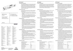
Installation instructions GEZE SecuLogic FTV 320 escape door lock
DE | Deutsch Produktbeschreibung GB | English Product description Die Fluchttürverriegelung FTV 320 ist Bestandteil des GEZE SecuLogic Rettungswegsystems und dient der Steuerung und Überwachung von elektrisch verriegelten Türen im Verlauf von Flucht-und Rettungswegen. Nach berechtigter Freischaltung oder durch Drücken der Nottaste der GEZE Türzentralen TZ 300 / TZ 320 entriegelt die FTV 320 die Tür elektrisch und gibt diese frei. Sicherheitshinweise GEZE SecuLogic FTV 320 DE Montagehinweise GB Installation instructions FR Consignes de montage Fluchttürverriegelung Emergency exit lock Verrou d‘issue de secours Germany GEZE Sonderkonstruktionen GmbH Planken … 97944 Boxberg-Schweigern Tel. +49 (0) 7930 9294 … Fax +49 (0) 7930 9294 10 E-Mail: sk.de@geze.com GEZE GmbH Niederlassung Süd-West Tel. +49 (0) 7152 203 594 E-Mail: leonberg.de@geze.com GEZE GmbH Niederlassung Süd-Ost Tel. +49 (0) 7152 203 6440 E-Mail: muenchen.de@geze.com GEZE GmbH Niederlassung Ost Tel. +49 (0) 7152 203 6840 E-Mail: berlin.de@geze.com GEZE GmbH Niederlassung Mitte/Luxemburg Tel. +49 (0) 7152 203 6888 E-Mail: frankfurt.de@geze.com GEZE GmbH Niederlassung West Tel. +49 (0) 7152 203 6770 E-Mail: essen.de@geze.com GEZE GmbH Niederlassung Nord Tel. +49 (0) 7152 203 6600 E-Mail: hamburg.de@geze.com GEZE Service GmbH Tel. +49 (0) 1802 923392 E-Mail: service-info.de@geze.com China GEZE Industries (Tianjin) Co., Ltd. E-Mail: chinasales@geze.com.cn www.geze.com.cn Russia OOO GEZE RUS E-Mail: office-russia@geze.com www.geze.ru GEZE Industries (Tianjin) Co., Ltd. Branch Office Shanghai E-Mail: chinasales@geze.com.cn www.geze.com.cn Scandinavia – Sweden GEZE Scandinavia AB E-Mail: sverige.se@geze.com www.geze.se GEZE Industries (Tianjin) Co., Ltd. Branch Office Guangzhou E-Mail: chinasales@geze.com.cn www.geze.com.cn Scandinavia – Norway GEZE Scandinavia AB avd. Norge E-Mail: norge.se@geze.com www.geze.no GEZE Industries (Tianjin) Co., Ltd. Branch Office Beijing E-Mail: chinasales@geze.com.cn www.geze.com.cn Scandinavia – Denmark GEZE Danmark E-Mail: danmark.se@geze.com www.geze.dk France GEZE France S.A.R.L. E-Mail: france.fr@geze.com www.geze.fr Singapore GEZE (Asia Pacific) Pte, Ltd. E-Mail: gezesea@geze.com.sg www.geze.com Hungary GEZE Hungary Kft. E-Mail: office-hungary@geze.com www.geze.hu South Africa GEZE Distributors (Pty) Ltd. E-Mail: info@gezesa.co.za www.geze.co.za Iberia GEZE Iberia S.R.L. E-Mail: info@geze.es www.geze.es Switzerland GEZE Schweiz AG E-Mail: schweiz.ch@geze.com www.geze.ch India GEZE India Private Ltd. E-Mail: office-india@geze.com www.geze.in Turkey GEZE Kapı ve Pencere Sistemleri E-Mail: office-turkey@geze.com www.geze.com Austria GEZE Austria E-Mail: austria.at@geze.com www.geze.at Italy GEZE Italia S.r.l E-Mail: italia.it@geze.com www.geze.it Ukraine LLC GEZE Ukraine E-Mail: office-ukraine@geze.com www.geze.ua Baltic States GEZE GmbH Baltic States office E-Mail: office-latvia@geze.com www.geze.com GEZE Engineering Roma S.r.l E-Mail: roma@geze.biz www.geze.it United Arab Emirates/GCC GEZE Middle East E-Mail: gezeme@geze.com www.geze.ae Benelux GEZE Benelux B.V. E-Mail: benelux.nl@geze.com www.geze.be www.geze.nl Bulgaria GEZE Bulgaria - Trade E-Mail: office-bulgaria@geze.com www.geze.bg Poland GEZE Polska Sp.z o.o. E-Mail: geze.pl@geze.com www.geze.pl Romania GEZE Romania S.R.L. E-Mail: office-romania@geze.com www.geze.ro GEZE GmbH Reinhold-Vöster-Straße 21–29 71229 Leonberg Germany United Kingdom GEZE UK Ltd. E-Mail: info.uk@geze.com www.geze.com Tel.: 0049 7152 203 … Fax: 0049 7152 203 310 www.geze.com The emergency exit lock FTV 320 is part of the GEZE SecuLogic emergency exit system and is used to control and monitor electrically locked doors on emergency exits. The FTV 320 unlocks the door electrically following authorised activation or by pushing the emergency push button on the GEZE door control units TZ 300 / TZ 320 and releases it. Safety instructions Für die Sicherheit von Personen ist es wichtig, nachstehenden Hinweisen Folge zu leisten. Diese Anweisungen sind aufzubewahren! àà Die FTV 320 ist nach geltenden Normen und Bestimmungen geprüft und als geeignet anerkannt: EltVTR; EN 1670; EN 61000. àà Die Montage an Feuer- und Rauchschutztüren ist nur erlaubt, wenn die Verwendbarkeitsnachweise für diese Türen dieses vorsehen und deren Maßgaben beachtet werden. àà Es sind die Sicherheitshinweise des zugelassenen Rettungswegsystems zu beachten. Produkthaftung 159494-00 FR | Français Description du produit àà Gemäß der im Produkthaftungsgesetz definierten Haftung des Herstellers für seine Produkte sind die hier enthaltenen Hinweise zu beachten. Die Nichtbeachtung entbindet den Hersteller von seiner Haftungspflicht. àà Jede elektrische Verriegelung einer Tür im Verlauf eines Rettungsweges bedarf einer Befreiung von entgegenstehenden Vorschriften im Einzelfall. àà Nur Sachkundige, die von GEZE autorisiert sind, dürfen Montagen, Funktionsprüfungen und Wartungen durchführen. àà Es dürfen keinerlei mechanische oder elektrische Veränderungen vorgenommen werden. Auch das Entfernen oder Austauschen des Stulps schließt jede Haftung von GEZE für daraus resultierende Schäden aus. Montagehinweise Consignes de sécurité générales To ensure personal safety it is important to follow the notes below. These instructions must be kept. àà The FTV 320 has been tested according to applicable standards and stipulations and found to be suitable: EltVTR; EN 1670; EN 61000. àà Installation on fire and smoke protection doors is only permitted if the proofs of application suitability for these doors include this and their specifications are heeded. àà The safety instructions for the approved emergency exit system must be followed. Product liability Technische Daten àà In compliance with the manufacturer’s product liability as defined in the German “Product Liability Act”, the instructions included here must be noted and followed. Failure to comply releases the manufacturer from his statutory liability. àà Every electrical locking of a door on a rescue route must be exempted from contradictory regulations in individual cases. àà Only specialists authorised by GEZE are permitted to carry out installation, function checks and after-sales service maintenance work. àà No mechanical or electrical modifications may be made. GEZE shall not be liable for injuries or damage resulting from the removal or replacement of the front metal. 15,2 x 138,8 x 37,3 24 àà Conformément à la responsabilité du fabricant vis-à-vis de son produit définie dans la loi relative à la responsabilité du fait des produits, les informations contenues dans le présent document doivent être respectées. Le non-respect libère le fabricant de son devoir de responsabilité. àà Chaque verrouillage électrique d’une porte dans une issue de secours nécessite exonération des dispositions contraires au cas pas cas. àà Seules les personnes qualifiées dûment autorisées par GEZE doivent réaliser les opérations de montage, de contrôle du fonctionnement et de maintenance. àà Aucune modification mécanique ou électrique ne doit être apportée. Le retrait ou le remplacement de la battée libère GEZE de son devoir de responsabilité pour les dommages consécutifs. Consignes de montage àà The FTV 320 is installed on the left hand (ISO 6) or right hand (ISO 5) side, horizontally or vertically, in the door leaf or frame. àà The tapered side of the control latch must be pointing in the direction of closing movement when installed. àà Care must be taken that no foreign material or filings get into the locking element. àà The use of lubrication or gliding agents is prohibited. àà Fixing screws are not supplied by GEZE and must be selected according to the specific material. àà The latches of the FTV 320 must be able to engage freely in the strike plate so that the door can close perfectly. àà Genuine GEZE accessories must be used. Technical data Hauptmaße [mm] (B x H x T) Betriebsspannung [V DC] Stromaufnahme [mA] in verriegelten Zustand kurzzeitig bei Verriegelungsvorgang Betriebstemperatur [°C] Pour la sécurité des personnes, il est essentiel de respecter les consignes suivantes. Ces instructions sont à conserver ! àà Le FTV 320 est certifié selon les normes et dispositions applicables et reconnues comme adaptées : EltVTR; EN 1670; EN 61000. àà Le montage sur des portes coupe-feu et pare-fumée n’est autorisé que si ces portes disposent d’une preuve de conformité et que les conditions prévues sont respectées. àà Les consignes de sécurité du système pour issues de secours homologué doivent être respectées. Responsabilité du fait des produits Installation details àà Die Montage der FTV 320 erfolgt DIN links, DIN rechts, waagerecht oder senkrecht, in Türblatt oder -rahmen. àà Die abgeschrägte Seite der Steuerfalle muss beim Einbau in Schließrichtung zeigen. àà Es ist darauf zu achten, dass keine Fremdteile oder Feilspäne in das Verriegelungselement gelangen. àà Das Anwenden von Schmier- oder Gleitmittel ist untersagt. àà Befestigungsschrauben sind nicht im Lieferumfang enthalten und müssen materialspezifisch ausgewählt werden. àà Die Fallen der FTV 320 müssen ungehindert in das Schließblech greifen können, sodass die Tür einwandfrei schließt. àà Es ist original GEZE-Zubehör zu verwenden. Le verrouillage pour issue de secours FTV 320 fait partie du système pour issues de secours GEZE SecuLogic et sert à commander et à contrôler les portes à verrouillage électrique dans les issues de secours. Une fois le déclenchement autorisé ou une fois le bouton de secours enfoncé sur la centrale de la porte GEZE TZ 300 / TZ 320, le système FTV 320 déverrouille la porte et la débloque. àà Le montage du système FTV 320 peut être effectué selon DIN à gauche, selon DIN à droite, à l’horizontale ou à la verticale, dans le vantail de la porte ou dans le dormant. àà Le côté biseauté du pêne de commande doit indiquer le sens de fermeture lors du montage. àà Il est nécessaire de veiller à ce qu’aucune pièce externe et aucun élément de limaille ne se coince dans l’élément de verrouillage. àà L’utilisation de graisse lubrifiante ou de lubrifiant est interdite. àà Les vis de fixation ne sont pas fournies à la livraison et doivent être choisies de façon spécifique en fonction du matériel. àà Les pênes du système FTV 320 doivent pouvoir s’insérer sans obstacle dans la tôle de fermeture afin que la porte puisse se fermer sans difficulté. àà Des accessoires d’origine GEZE doivent être utilisés. Caractéristiques techniques … x … x … 24 100 240 -20/+60 Main dimensions [mm] (W x H x D) Operating voltage [V DC] Current consumption [mA] in locked state briefly during the locking process Operating temperature [°C] 100 240 -20/+60 Dimensions [mm] (L x H x P) Tension de service [V DC] Consommation de courant [mA] dans un état verrouillé À court terme lors du processus de verrouillage Température de service [°C] Eignungsnachweis EltVTR Aufbruchfestigkeit [N] … Fallenvorlast [N] Spaltmaß [mm] 100 240 -20/+60 Suitability certificate EltVTR Certificat de conformité EltVTR Break-open resistance [N] … Résistance à la rupture [N] … Latch sideload [N] … Précontrainte du pêne [N] … 5±2 Gap dimensions [mm] 5±2 Écartement de la fente [mm] 5±2 Weitere Informationen und Support im Internet unter www.geze.com Visit www.geze.com for further information and support. 15,2 x 138,8 x 37,3 24 Plus d‘informations et de conseils sur Internet sur www.geze.com TZ 300 TZ 320 FTV 320 FTV 320 TZ 300 TZ 320 FTV 320 FTV 320 Li-Y(ST)Y … x 0,25 mm2, max. 100 m J-Y(ST)Y … x … x 0,6 mm, max. 100 m TZ 300 / TZ 320 FTV 320 X101 / X106 (orange) + … 5 - … 6 verriegelt / locked / verrouillé 14 24 V DC … 14 Verriegelungszustand Locking mode … État du verrouillage geschlossen / closed / fermé 15 Verriegelung Locking Verrouillage + 24 V - GND Eingang / Input / Entrée COM1 15 Türzustand Door mode … État de la porte COM2 … COM1 SA Sabotage … 1 NO NO optional / en option … 52 53 … 2 NO 2x 5×35 2x M5×20 … 2
PDF | 3 MB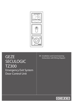
GEZE TZ 300 emergency exit system door control unit
GEZE SECULOGIC TZ300 EN Installation and Commissioning Instructions with Wiring Diagram Emergency Exit System Door Control Unit … SECULOGIC TZ300 Contents … 1. About this document … … . … . … . … . Product description … Related documents … Key to symbols … Abbreviations … 2. Safety and responsibility … … . … . … . General safety instructions . … Target readership and qualifications … Product liability … 3. Installation and assembly … … . … . … . … . … . Preconditions … Installing the flush-mounted door control unit … Fitting the surface-mounted door control unit … Replacing the lock cylinder … 11 Fitting a safety cylinder, length 40/10 … 11 4. Commissioning … 12 … . … . … . … . Preconditions . … 12 Settings … 12 Description of basic functions … 12 Fire detection system (BMA), hazard alert system (GMA), smoke and heat extraction system (RWA) … 13 5. Operation … 14 … . … . … . … . … . … . Controlling door control unit TZ300 with the key switch … 15 Opening doors in emergencies and triggering alarm … 16 Cancelling alarms … 17 Alarm signal … 18 Removing alarms and system faults … 19 Mains failure … 19 6. Wiring diagram … 20 … . … . … . … . … . … . … . … . … . General information … 20 Markings … 20 Current consumption … 20 Door control units … 21 Locking elements … 26 Key switch … 29 Access control … 32 Timer … 33 IQ Lock EM, lever locks … 34 7. … . … . … . Appendix … 36 Commissioning check list … 36 Glossary of terms … 37 Data sheets … 38 SECULOGIC TZ300 … About this document About this document These instructions describe the installation and commissioning of the GEZE TZ300 door control unit. … Product description The GEZE door control unit is part of the SecuLogic emergency exit system. It is designed for controlling and monitoring electrically interlocked emergency exit doors. It secures doors along emergency exit routes against unauthorized access. At the same time the built-in emergency stop pushbutton allows instant passage in the event of an emergency. Through a built-in interface a smoke and heat extraction, burglar alarm or hazard alert system can be connected, which unlocks the door in an emergency to allow an escape from the building. External signal transmitters, such as alarm bells or warning lights can be connected as well as an alarm signalling interface to the building services management system. Built-in buzzers and LEDs provide visual and audible indication when an alarm has been triggered. … Related documents All components are supplied with data sheets containing their technical specifications. These data sheets, as well as further documentation, is available on the Internet under www.geze.de/SecuLogic. … Key to symbols Warning In these instructions, warnings are used to warn against material damage and injuries. XX Always read and observe these warnings. XX Follow all instructions marked with the warning symbol and the word WARNING. Warning symbol Warning WARNING Meaning Danger for people. Serious or fatal injury can occur if these instructions are not observed. Further symbols used in these instructions Important information and technical notes are emphasised to illustrate the correct operation. Symbol Meaning means “Important note” means “Additional information” XX Symbol for a user action. Observe the sequence if there are several action steps. … About this document … Abbreviations Abbreviation AKRR BLE220 BMA FS FTÖ GCDU100 GCDU200 GCFP401 GCRR200 GCVR200 GLT GMA IQ Lock C IQ Lock EL IQ Lock EM IQ Lock M KZF MA500 NC NO NOT320 PSU OKFF RR RWA SCT221 SCT222 SCT320 SHB220 SLE220 SLH220 TZ300S TZ300S ZSU … SECULOGIC TZ300 Meaning Feedback contact interlocked (actuated by the anchor) Flashlight Fire detection system Latch lock Emergency exit door opener Single-door unit Door unit Fingerprint RFiD card reader RFiD card reader Building services management Hazard alert system Self-locking contact lock Self-locking motor lock Self-locking lever lock Self-locking mechanical panic lock Short-term release Holding magnet Floating NC (normally closed) contact Floating NO (normally open) contact Emergency button Power supply unit Upper edge of finished floor “Door closed” feedback contact (actuated through sliders on the latch) Smoke and heat extraction system Key-operated pushbutton, single-pole pushbutton (NO), extendable to single-pole reversing (two NO) Key switch with LED indicator, single-pole reversing (two NO) Key switch, single-pole reversing (two NO) Alarm bell with flashlight Signal lamp Alarm bell Door control unit with key switch (connection through ribbon cable) Door control unit with key switch and built-in PSU Timer SECULOGIC TZ300 … Safety and responsibility Safety and responsibility The GEZE door control unit has been designed according to the latest technical standards and acknowledged safety rules and regulations. Dangers can, nevertheless, occur in its installation and use. You must therefore observe the following instructions. … General safety instructions XX XX XX XX XX XX XX XX Installation, commissioning and repairs must be performed only by GEZE-authorized specialists. Use only genuine GEZE parts for repairs. GEZE accepts no liability for damage arising from unauthorized modifications to the installation. Primary building safety measures must be taken by the owner. Cables must be laid according to standards VDE 0100 and VDE 0815. To prevent unauthorized access, never leave the key in the key switch. Doors with electrical locks along escape routes should be inspected annually by a specialist. The specialist must issue a certificate verifying the periodic inspection, which the owner must submit to the building inspectorate on request. The inspection can be performed by a GEZE service technician or a GEZE-authorized service provider as part of a maintenance contract. In addition, GEZE recommends a monthly inspection of the emergency exit system for visible damage and faults by the owner. Any identified damage or faults must be rectified immediately by a GEZE service technician or a GEZE-authorized service provider. Intended use The GEZE door control unit is intended for controlling and monitoring electrically locked emergency exits. Thirdparty products must be used only after consultation with GEZE. Improper use Improper use includes the connection of any products that are not expressly approved by GEZE. … Target readership and qualifications Installation, assembly, commissioning and repairs must be performed only by GEZE-authorized specialists. … Product liability àà According to manufacturers’ liability for their products as defined in the German product liability act, the information contained herein and in the associated installation instructions and wiring diagrams (product information and intended use, incorrect use, product performance, product maintenance, obligation to inform and obligation to provide instruction) must be observed. Non-observation frees the manufacturer from their liability. àà Installation, function testing and maintenance must be performed only by GEZE-authorized personnel. GEZE accepts no liability for damage arising from unauthorized modifications to the installation. àà A combination with third-party devices invalidates GEZE’s warranty. For repair and maintenance, use only original GEZE parts. … Installation and assembly … SECULOGIC TZ300 Installation and assembly Warning! Risk of death through electric shock. XX Installation and assembly must be performed only by GEZE-approved specialist personnel. XX Check that all cables are voltage-free before installation. … Preconditions àà àà àà àà àà … Cables are routed according to GEZE cabling diagram Miniature circuit-breakers as primary, mains-side disconnectors Observation of standards VDE 0100 und VDE 0815 for laying cables Tamper-proof cable routing according to VDE 0833 (surface-mounted cables in steel conduit) For flush-mounted cabling, flush-mounted sockets (depth … mm) at a mounting height of 850 mm from floor surface and up to 1200 mm for the emergency button Installing the flush-mounted door control unit These instructions describe the recommended installation of the a flush-mounted door control unit using the TZ300SN as an example. … 2 … 7 … 6 … 1 … 3 … 5 … 7 … Emergency exit label Frame PSU NET220 Terminal blocks Ribbon cable Control unit with emergency pushbutton TST300 Key switch SCT320 SECULOGIC TZ300 XX XX Installation and assembly Lay mains cable and ribbon cable in the flush-mounted sockets. Connect cable to terminal blocks according to wiring diagram. ,5 62 60 850 - 1200 71 XX XX 71 Connect and fit the PSU. Connect the key switch door control module with the ribbon cable. … Installation and assembly XX SECULOGIC TZ300 Fit the terminal blocks to the back of the door control unit. C D C D XX Fit the door control unit. Fit the green adhesive frame. XX Test the unit’s function. XX … SECULOGIC TZ300 … Installation and assembly Fitting the surface-mounted door control unit … 1 Door control unit TZ300SN … Terminal blocks … XX Open the housing. … Installation and assembly Fit the wall-mounting bracket near the door (height of emergency button: 850 mm – 1200 mm from floor surface). 850 - 1200 XX SECULOGIC TZ300 Take off the mains connection cover. Connect the 230 V cable to the screw terminals of the PSU and refit the cover. XX Connect cable to terminal blocks according to wiring diagram. XX Fit the terminal blocks to the back of the door control unit. XX Secure loose cables with cable ties. XX XX Hook in housing and secure with screws. Fit the cover of the emergency button. XX Test the unit’s function. XX Apply the labels “EMERGENCY” and “Press only in emergency” in the required language on the provided fields on the emergency exit sign. The required adhesive labels are supplied separately in English, French, German and Norwegian. XX XX 10 SECULOGIC TZ300 … Replacing the lock cylinder The lock cylinder must fulfil the following requirements: àà Profile half-cylinder, 40 mm (30/10) àà Eight-way adjustable When the plant is in operation, disable tamper switch. àà To do this, turn key to left for ten seconds. Right LED lights up green. The left LED goes out. Tamper alarm function is disabled for two minutes. XX Take housing off the wall bracket. XX Unscrew key switch. XX Release cap screw and remove the lock cylinder. XX … Fitting a safety cylinder, length 40/10 If using a safety cylinder with 50 mm (40/10), use the spacers between key switch and housing. Fit the spacers before the carrier plate; this moves the complete fixture to the back by 10 mm. The spacer set is not included as standard with the door control unit. The set also contains four longer screws, which must be used instead of the existing screws. XX XX XX XX Replace the lock cylinder. Fit a new lock cylinder and secure with cap screw. Reassemble the door control unit in reverse order to disassembly. Test the unit’s function. 11 Commissioning … Commissioning … Preconditions SECULOGIC TZ300 Doors with electrical locks along escape routes must be taken into operation after the manufacturer has certified their suitability for the intended purpose. In addition, the correct installation and correct function of the electrical lock must be verified by a specialist. … .1 Tamper switch TST300 When operating voltage is applied to the TZ300, a tamper alarm is triggered if the emergency button’s hood is not fitted. … .2 Tamper switch SCT320 (on UP only) When operating voltage is applied to the TZ300, a tamper alarm is triggered if the emergency button’s hood is not fitted. If the tamper switch of the key switch is not to be evaluated, you must fit a jumper between terminals … and 54. … .3 Disabling the tamper alarm For maintenance, the tamper alarm can be disabled for a limited time. To do this, turn the built-in key switch to the left for about ten seconds. This disables the tamper alarm for about two minutes. While it is disabled, the right LED is lit green and the left LED is off. To reenable the tamper alarm before the two minutes are up, turn the built-in key switch to the right. The door control unit is then unlocked. To lock it, turn the key switch to the right again. … Settings No settings can be made or changed on the door control unit. All values, such as short-term release, cancelling, pre-alarm, etc. are permanently set. … Description of basic functions … .1 Short-term release (KZF) Short-term release releases the emergency door protection for a limited time. During this time, access through the door is possible without triggering an alarm. It is activated with the built-in key switch or an external actuator connected to the short-term release input. The short-term release duration is about 20 seconds. … .2 Cancellation of short-term release When short-term release is active, the door locks prematurely when it is closed before the short-term release time has expired. This prevents unauthorized access through the door after an authorized person has gone through. … .3 Retriggering on short-term release If the short-term release function is triggered again while the function is still active, the short-term release period starts again. … .4 Pre-alarm If the door is passed through after the short-term release time has expired, an audible signal is issued to warn the user that the short-term release time has expired. The pre-alarm duration is 60 seconds. If the door is closed while a pre-alarm is active, the door is locked again automatically and the pre-alarm is reset. 12 SECULOGIC TZ300 … .5 Commissioning Door alarm If the pre-alarm time is exceeded, the door alarm is triggered. This must then be reset with the built-in key switch or with a new short-term release command. If the door is closed while the door alarm is active, it locks and can be unlocked again only after the alarm has been reset (except when the emergency button is pressed or emergency unlocking is triggered). The door alarm is also triggered when the door is opened forcefully. … .6 Unlocked The power supply to the locking element is permanently interrupted. The door can be passed through without triggering an alarm. … .7 Locked The locking element is energized through the door control unit. The emergency door protection is active and unauthorized people can open the door only by pressing the emergency button, which triggers an alarm. … .8 Emergency unlocking The TZ300 can be unlocked in an emergency by the fire detection, burglar alarm or hazard alert system. This is a non-safety-relevant interruption of the power supply to the locking element. When the BMA, GMA or RWA signal is cancelled, the alarm is automatically reset after 60 seconds. … .9 Direct unlocking (according to EltVTR) Safety-relevant interruption of the power supply to the electrical lock through an NC contact when the emergency button is pressed. … Fire detection system (BMA), hazard alert system (GMA), smoke and heat extraction system (RWA) … .1 Alarm triggers If the BMA, GMA or RWA signal of a door control unit is applied, it is unlocked and a local alarm is triggered (audible through built-in buzzer and visual through built-in LED). The system remains unlocked as long as the signal is applied and until the alarm has been reset. See … .3, “Resetting the alarm”. The alarm is triggered through a floating NC contact. If no BMA, GMA or RWA exists, a 2K resistor must be fitted across the Fire Detection System input (terminals … and 10, orange terminal field. This is the as-supplied state. If a BMA or GMA system is connected, the 2K resistor at the emergency unlocking input of the TZ300 (terminals … and 10) must be removed and connected in series with the NC contact of the BMA or GMA. … .2 Cable monitoring according to prEN 13637 For installations according to prEN 13637 the cable between fire detection system and door control unit must be monitored. A 2k resistor must be fitted in series with the NC contact at the fire detection system output for this purpose. … .3 Resetting/acknowledging the alarm When the BMA signal is cancelled, the alarm is automatically reset after 60 seconds. The visual and audible signal at the TZ300 goes out and the door control unit locks the door. The system can be reset before the 60 seconds have expired with the built-in key switch of the TZ300. To unlock the system after a reset, turn the key to the left for more than one second. To lock the system after a reset, turn the key to the right. 13 Operation … SECULOGIC TZ300 Operation … 2 … Emergency exit label … Key switch … Control unit with emergency button … “Locked” LED … “Door state” LED … “Alarm” LED … No. … 2 … 14 Indicator Colour Meaning Red Locked Green Unlocked Green flashing (every second) Short-term release Red Door closed Green Door open Yellow Alarm Yellow flashing (every second) Pre-alarm Yellow flashing Fault SECULOGIC TZ300 … Operation Controlling door control unit TZ300 with the key switch Unlocking the door When the system is unlocked, the locking elements are disabled and the door can be opened. XX Turn the key to the left and hold it for about one second. … 1 … LED … lights up green. The door is unlocked. Locking the door When the system is unlocked, the locking elements are enabled and the door can not be be opened. Preconditions: The door is closed; otherwise a pre-alarm is triggered. XX … Turn the key to the right. … 3 LEDs … and … light up red. The door is locked. 15 Operation SECULOGIC TZ300 Unlocking the door temporarily (short-term release = 20 seconds) With the short-term release function, the door can be unlocked with the key switch for 20 seconds. When this time has expired, the door is locked again. àà If the door is not closed after short-term release time has expired, a pre-alarm is issued. àà If the door is closed after the short-term release time has expired, the door is locked again. àà If the short-term release function is triggered again while the function is still active, the short-term release period starts again (is retriggered). Precondition: The door is locked. XX Turn the key to the right. … 2 … LED … flashes green. The door remains unlocked for the set period of 20 seconds. On cancellation the LED lights up red. … Opening doors in emergencies and triggering alarm When the emergency button is pressed the door’s locking elements are de-energized and the door can be opened (direct unlocking). If a connected fire detection or similar system triggers, the locking elements are de-energized automatically to release the door (emergency unlocking). XX … Press the emergency button. … 3 LED … lights up green and LED … lights up yellow. The door is unlocked. The alarm is triggered. 16 SECULOGIC TZ300 … Operation Cancelling alarms Alarms of the door control unit remain active until their cause has been eliminated and the alarm is acknowledged at the door control unit. (Exception: emergency unlocking through BMA,GMA or RWA, after which the alarm is automatically reset after 60 seconds; see section … .3.) … .1 Resetting emergency button When the emergency has passed, the emergency button must be reset. XX Remove emergency button cover. XX Turn emergency button to the right. The emergency button returns to its normal state. XX Refit the cover. XX Acknowledge the alarm. … .2 Acknowledge alarm Precondition: The alarm cause has been eliminated. To acknowledge the alarm and lock the door XX Turn the key to the right To acknowledge the alarm and unlock the door XX Turn the key to the left The door alarm can also be acknowledged through the short-term release input. A tamper alarm can be acknowledged only 30 seconds after the alarm cause has been eliminated. For the duration of the tamper alarm the TZ300 remains locked. It can, however, be unlocked with the emergency button. If the alarm can not be acknowledged with the key switch, a new alarm may be active. If, for example, the cover was not refitted after resetting the emergency button, a tamper alarm is triggered when emergency unlocking is acknowledged, and the door control unit locks the door. This is indicated by a change in the sound of the audible signal. 17 Operation … SECULOGIC TZ300 Alarm signal Misuse of the system and emergency situations are indicated by a built-in buzzer and yellow alarm LED 3. An alarm can, in principle, be acknowledged only when its cause has been removed. Alarm Pre-alarm Alarm LED Alarm bell Yellow flashing light Acoustic signal, … beeps (1 s on, … s off) Door alarm Yellow continuous light Acoustic signal, … seconds continuous Tamper alarm Yellow continuous light Acoustic signal, … beeps Alarm Yellow continuous light Acoustic signal, … seconds continuous - Unlocking through emergency button - Triggering trough BMA/GMA System fault 18 Yellow flashing light No acoustic signal at … second interval SECULOGIC TZ300 … Operation Removing alarms and system faults Alarm state Cause of alarm Pre-alarm Door not closed after unlocking period has expired. No closed signal No closed signal Door alarm Elimination of alarm cause XX XX XX XX Tamper alarm No locked signal Tamper switch of door control unit not closed (on UP only). XX XX XX XX Alarm Key switch tamper switch not closed. Emergency button of TZ300 pressed (direct unlocking). Fuse in TST300 blown. XX XX XX Emergency unlocking through connected BMA, GMA or RWA. XX XX 2K resistor between terminals … and 10 not set and no BMA, GMA or RWA connected. Locking element connected with reversed polarity. Emergency button LED goes on and off. Other LEDs remain off. (With PSUs NET220 und NT19.2-24. With larger PSUs the fuse blows.) Locking element not connected. Jumper on FTÖ331U was not removed. FTÖ332 is connected without RP220. Short-circuit in the supply line of the lockingelement. XX XX XX XX XX XX XX XX Controller defective XX Close door. Unlock door. Close door. Check door contact. Check locking element. Close contact. Fit cover. After suppression time,acknowledge alarm. Reset door control unit emergency button. Check fuse. Replace fuse. Check BMA, GMA or RWA and switch off emergency unlocking signal. Check input of affected door control unit. Fit a 2K resistor between terminals … and 10. Immediately isolate from the power supply and connect correctly. Connect locking element. Remove jumper on FTÖ331. Check locking element supply line for short-circuit. Connect FTÖ332 with RP220. Press emergency button. Release (pull out) emergency button. Replace door control unit. When the alarm cause has been remedied, the alarm must be acknowledged with the built-in key switch. … Mains failure When mains power is restored, the door control unit is always in operating state Locked. If an alarm is active when mains power is restored, the door control unit is in operating state Alarm. Operating mode before mains failure Operating mode after mains failure Locked Permanent unlocking Short-term release Alarm Locked Locked Locked Alarm or acknowledge alarm if cause no longer exists 19 Wiring diagram SECULOGIC TZ300 … Wiring diagram … General information Unless otherwise stated, the wiring diagrams apply to surface-mounting versions and flush-mounting versions from TS300, software version … . … Markings The wiring in these wiring diagrams are marked as follows: … Colour Former designation to DIN 47002 New designation to DIN IEC 757 Colour Former designation to DIN 47002 New designation to DIN IEC 757 Black Brown Red Orange Yellow Green sw br rt or ge gn BK BN RD OG YE GN Blue Violet Grey White Pink Turquoise bl vi gr ws rs tk BU VT GY WH PK TQ Current consumption When connecting external devices, observe the overall power consumption. àà Output rating for external devices through standard PSU: àà Flush-mounted version (NET220): 24 V DC, max. 350 mA àà Surface-mounted version (NT19.2-24): 24 V DC, max. 650 mA àà Output rating for external devices through external PSU (Net24-5, Logo): … A … .1 Consumer Consumption in mA (approx.) Consumer Consumption in mA (approx.) Door control unit TZ300 Control module TST300 120 100 Holding magnet MA500 Emergency exit door opener FTÖ331 Emergency exit door opener FTÖ332 Relay card RP220 250 160 105 10 Numerical code lock CTI / CTS V Signal lamp SLE220 Flashlight BLE220 Alarm bell with flashlight Alarm bell SLE220 Key switch with LED SCT222 50 85 90 110 16 30 Single-door unit GCDU100 Door unit GCDU200 Master unit GCMU200 GCMDU200 Master unit GCMU524 30 120 120 120 130 Fingerprint reader GCFP401 Card reader GCRR200 Card reader GCVR200 Smoke switch RS5 200 100 100 19 IQ Lock EM / EM DL, 24 V version IQ Lock EL / EL DL with controller MST210 210 250 Examples for calculating the total power consumption Example 1: Single-leaf emergency door with 1×TZ300SN UP (120 mA), 1× FTÖ331 (160 mA) and 1× SLE220 (85 mA). Total current consumption of all devices = 365 mA; external devices = 245 mA (without TZ300) Conclusion: PSU NET220 with 500 mA of the TZ300SN UP is sufficient. Example 2: Two-leaf emergency door with TZ300SN AP (120 mA), 2× MA500 (250 mA), SCT222 (30 mA) and RP220 (10 mA) IQ Lock EM DL 24V (210 mA) Total current consumption of all devices = 870 mA; external devices = 750 mA (without TZ300) Conclusion: PSU NT19.2-24 with 800 mA of the TZ320SN AP is not sufficient. Solution 1: For IQ Lock EM DL, use separate PSU (NT6.3-24, 260 mA, No. 109637) Solution 2: Use TZ300S without PSU and draw power from external PSU. (e.g. NT24-5, 24 V, … A No. 111182 or Siemens Logo 24 V, … A, No. 078401) 20 SECULOGIC TZ300 … Wiring diagram Door control units Programming interface orange Door LED blue Latch LED Emergency button LED red Tamper switch Buzzer Alarm LEDs … .1 Door control unit TZ300 (terminals, fuses) Fuse Name Value Meaning F1 … A, SMF 125 V, quick-acting 24 V external Operator control and display elements àà Latch LED àà Door LED àà Alarm LED àà Buzzer (75 dB at about 50 cm distance) Technical specifications Current consumption: 100mA Supply voltage for external devices: àà with standard PSU of the TZ300: àà with external PSU: UP: NET220, max. 350 mA; AP: NT19.2-24, max. 650 mA max. 800 mA (use only GEZE-approved PSUs) Terminal assignment Max. cable cross-section for screw and plug-in terminals: … mm² X103 X100 X101 X102 Terminal blade terminal for GEZE key switch red terminal field … 3 orange terminal field … 6 14 15 … 2 … 10 … Blue terminal field … 22 21 20 … Function Supply GND 24 V DC supply Locking element, +, 24 V DC Locking element, -, GND Door locked feedback Door closed feedback 24 V DC 24 V DC Brief unlocking input Emergency unlocking input 24 V DC 24 V DC NO, alarm output Com, alarm output Max. … A, 24 V DC NC, alarm output GND 21 Wiring diagram … .2 SECULOGIC TZ300 Notes about the wiring diagram The notes apply for the following wiring diagram of the various versions of the TZ300. 1) Building mains fuse. 2) The primary and secondary sides must be spatially separated. For the TZ300S the PSU must be fitted externally. 3) TZ300SN UP: Protection class II, PE (protective earth) conductor is not connected. TZ300SN AP: Protection class I with PE conductor testing according to VDE0100. 4) In delivery state the 2K resistor is fitted. When connecting a BMA, GMA or RWA, remove the resistor and connect it in series with the NC contact of the BMA, GMA or RWA (see plan “Emergency unlocking through BMA, GMA or RWA”). 5) Contact closed when door closed. 6) When a GEZE alarm bell or siren is fitted, a jumper must be set. 22 SECULOGIC TZ300 … .3 Wiring diagram Door control unit TZ300S, TZ300SN blue For notes about the wiring diagram, see section … .2 23 Wiring diagram … .4 SECULOGIC TZ300 TZ300SN, TZ300S: Door monitor without locking element For use, for example, as door monitor Function: The door can be opened at any time through the panic handle. Opening the door without authorization triggers the door alarm, which, in turn, triggers a visual and acoustic alarm through the built-in signal generators. The door alarm remains active until the door is closed again and the alarm is reset with the built-in key switch or through the Short-term release input. Authorized access is possible with short-term release function or by permanently unlocking the door. X102 (blue) X100 (red) 24 V DC Lock SCT, KZF, acknowledge Unlock SCT, acknowledge Tamper GEZE SCT320 Key switch X102 or X103 Ribbon cable Connection to TST300 X103 TST300 Plug for GEZE key switch X100 (red terminal strip) Power supply unit Screw terminal Supply GND 24 V DC supply Relay card RP220 Nr. 102355 X101 (orange terminal strip) Locking + Locking Door locked Door contact 24 V DC Door closed 24 V DC Brief unlocking input Emergency unlocking input 24 V DC Temporary unlocking through: - External key switch - Access control - Cylinder contact - Button, etc. Floating NO contact required Caution: Order of terminals not as on terminal strip X102 (blue terminal strip) Alarm output max. … A, 24 V DC Signal lamp Alarm bell Optionally for additional acoustic and/or visual alarm signalling. Observe max. total power consumption of TZ300SN. 24 SECULOGIC TZ300 … .5 Wiring diagram Emergency unlocking through BMA, GMA or RWA For notes about the wiring diagram, see section … .2 25 Wiring diagram … SECULOGIC TZ300 Locking elements If the door has several unlocking elements, connect the coils in parallel and the feedback signal cables in series. (blue) Programming interface red … .1 Holding magnet MA500 (single-leaf doors) TST300 - X101 (orange terminal strip) Locking + Locking Door locked 24 V DC Door closed 5) Door contact 24 V DC … .2 Holding magnet MA500 (two-leaf doors) TST300 – X101 (orange terminal strip) Locking + Locking Door locked 24 V DC Door closed Door contact 26 Door contact SECULOGIC TZ300 … .3 Wiring diagram Emergency door opener TYP331U DIN right/left (single-leaf doors) X101 (orange terminal strip) FTÖ331U Locking + … 1 + Locking - … 2 - Door locked 14 … NO 24 V DC … 7 COM Door closed 15 … NC 24 V DC … 5 NO … COM … NC XX … .4 AKRR RR Caution: Sever red wire jumper (1–7) behind the terminal field of the FTÖ331U. Emergency door opener TYP331U DIN right/left (two-leaf doors) X101 (orange terminal strip) A B FTÖ331U FTÖ331U … 1 + A … + Locking - … 2 - B … - Door locked 14 … NO … NO 24 V DC … 7 COM … COM Door closed 15 … NC … NC … NO … NO … COM … COM … NC … NC Locking + XX … .5 AKRR RR AKRR RR Caution: Sever red wire jumper (1–7) behind the terminal field of the FTÖ331U. Emergency door opener TYP331 DIN right/left (single-leaf doors) FTÖ331 DIN right X101 (orange terminal strip) FTÖ331 DIN left Locking + … 5 + … Locking - … 6 - Door locked 14 … NO 24 V DC … 2 COM Door closed 15 … NC 24 V DC … RD NO GN COM BU NC … + … 1 - 14 … NO … 5 COM … NC RD NO GN COM BU NC 15 AKRR RR For notes about the wiring diagram, see section … .2 27 Wiring diagram … .6 SECULOGIC TZ300 Emergency door opener TYP331 DIN right (two-leaf doors) X101 (orange terminal strip) A B Locking + … 5 + A … + Locking - … 6 - B … - Door locked 14 … NO … NO 24 V DC … 2 COM … COM Door closed 15 … .7 AKRR … NC … NC RD NO RD NO GN COM GN COM BU NC BU NC … + RR A B Locking + … 2 + A Locking - … 1 - B Door locked 14 … NO 24 V DC … 5 COM Door closed 15 … NC RD NO GN COM BU NC AKRR RR Emergency door opener TYP332 (1-leaf doors) X101 (orange terminal strip) Locking + Locking Door closed 24 V DC 24 V DC Door locked Relay card RP220 No. 102355 28 RR Emergency door opener TYP331 DIN left (two-leaf doors) X101 (orange terminal strip) … .8 AKRR … - … NO … COM … NC RD NO GN COM BU NC AKRR RR SECULOGIC TZ300 Wiring diagram … Key switch … .1 Key switch SCT320 to short-term release AS … .2 Key switch SCT220 to short-term release orange terminal strip 24 V DC COM Brief unlocking input Closed on right Closed on left No. 115937, UP Jung AS500, WW No. 094170, UP Jung LS990, stainless steel No. 094012, UP GIRA E2, pure white … .3 Key switch SCT221/SCT to short-term release (orange terminal strip) 24 V DC Brief unlocking input SCT No. 117996 + 024467 UP AS500 SCT No. 117996 + 024467 + 120503 AP AS500 SCT221 No. 054240 + 024467 without PHZ UP SCT221 No. 054532 + 024467 without PHZ AP SCT221 No. 054245 + 024467 with PHZ UP SCT221 No. 054533 + 024467 with PHZ AP No. 094170, UP Jung LS990, stainless steel No. 094012, UP GIRA E2, pure white 29 Wiring diagram … .4 SECULOGIC TZ300 Key switch SCT320 for external control – unlocking, locking, short-term release unlocking and acknowledging alarms Connected through SCT320 of door control unit TZ300 key switch key switch 24 V DC 24 V DC Lock SCT, KZF, acknowledge Lock SCT, KZF, acknowledge Unlock SCT, acknowledge Unlock SCT, acknowledge Tamper Tamper No. 130370, UP GIRA E2, pure white No. 132278, UP GIRA E2, anthracite No. 131984, UP Jung AS500, WW … .5 Key switch SCT220 for external control – unlocking, locking, short-term release and acknowledging alarms Connected through SCT320 of door control unit TZ300 key switch 24 V DC COM Lock SCT, KZF, acknowledge Closed on right Unlock SCT, acknowledge Closed on left Tamper 30 No. 115937, UP Jung AS500, WW No. 094170, UP Jung LS990, stainless steel No. 094012, UP GIRA E2, pure white SECULOGIC TZ300 … .6 Wiring diagram Key switch with indicator SCT222 For connecting the SCT222, relay card RP220 is required in addition. red terminal strip Power supply unit Screw terminal Supply GND 24 V DC supply orange terminal strip Locking + Locking Door locked 24 V DC Door closed 24 V DC Door contact Brief unlocking input Emergency unlocking input 24 V DC Caution: Sever red wire jumper (1–7) behind terminal field of FTÖ331U Caution: Order of terminals not as on terminal strip Relay card RP220 Nr. 102355 blue terminal strip 24 V DC Alarm output max. … A, 24 V DC green-red LED Ribbon cable yellow LED Plug for GEZE key switch right contact Key switch Connection to TST300 24 V DC Lock SCT, KZF, acknowledge Unlock SCT, acknowledge left contact SCT222 UP No. 100064 SCT222 AP No. 100065 Tamper For notes about the wiring diagram, see section … .2 31 Wiring diagram SECULOGIC TZ300 … Access control … .1 Numerical code lock Toplock CTI, CTI B X102 (blue) or X100 (red) X101 (orange terminal strip) Brief unlocking input … .2 Numerical codelock Toplock CTS V, CTS BV Number codelock Toplock CTS V, CTS BV (orange terminal strip) 24 V DC Brief unlocking input 32 Evaluation unit SECULOGIC TZ300 … .3 Wiring diagram Access control Single-door control unit GCDU100 Door control unit GCDU200 (orange terminal strip) 24 V DC Brief unlocking input Optionally the GCDU100 can be supplied with power through the TZ300. Observe total power consumption! X100 (red terminal strip) Supply GND 24 V DC supply … Timer (orange terminal strip) 24 V DC Brief unlocking input Floating NO contact The door control unit is temporarily unlocked for the duration of the contact. 33 Wiring diagram SECULOGIC TZ300 … IQ Lock EM, lever locks … .1 IQ Lock EM power from TZ300 For connecting the IQ Lock EM, relay card RP220 is required in addition. X100 (red terminal strip) Power supply unit Screw terminal Supply GND 24 V DC supply X101 (orange terminal strip) Locking + Locking Door locked 24 V DC Door closed 24 V DC Door contact Brief unlocking input Emergency unlocking input 24 V DC Caution: Sever red wire jumper (1–7) behind terminal field of FTÖ331U Caution: Order of terminals not as on terminal strip Relay card RP220 Nr. 102355 Lock connection cable X102 (blue terminal strip) red wire Magnet + black wire Magnet - red/blue wire COM cylinder contact grey/pink wire NO cylinder contact Temporary unlocking through: - External key switch - Access control - Button, etc. Floating NO contact required Function: When the TZ300 is locked, the outer lever handle of the IQ Lock EM is disengaged. When the TZ300 is temporarily or permanently unlocked, the outer lever handle is engaged. Option 1: When the cylinder contact of IQ Lock is connected to the Temporary Unlocking input, cylinder operation through the key triggers temporary unlocking. At the same time, the TZ300 engages the outer lever handle. *) Observe total power consumption of the TZ300. If necessary, use a separate power supply unit. 34 SECULOGIC TZ300 … .2 Wiring diagram IQ Lock EM power from separate PSU For connecting the IQ Lock EM, relay card RP220 is required in addition. Power supply unit No. 109637 Function: When the TZ300 is locked, the outer lever handle of the IQ Lock EM is disengaged. When the TZ300 is temporarily or permanently unlocked, the outer lever handle is engaged. Option 1: When the cylinder contact of IQ Lock is connected to the Temporary Unlocking input, cylinder operation through the key triggers temporary unlocking. At the same time, the TZ300 engages the outer lever handle. For notes about the wiring diagram, see section … .2 35 Appendix … Appendix … Commissioning check list SECULOGIC TZ300 Yes Power supply OK Upper edge of all emergency buttons between 850 and 1200 mm from floor surface All emergency button labels applied Cables laid according to DIN VDE 0833, tamper-protected All screws of magnet mounting tightened Rubber buffers on screws of magnetic disc OK Magnet surfaces cleaned Door passage lights at least 2000 mm Emergency door opener fitted correctly and tamper-protected All cables connected, exposed cables insulated Emergency button illumination working “Emergency button” function OK Tamper switches working correctly Unlocking through key switch is working correctly Locking through key switch is working correctly Feedback from magnet and/or door opener working correctly Additional door contacts working correctly Door Leaf Open/Closed LED working correctly Door Locked/Unlocked LED working correctly Alarm/Fault LED working correctly 2K resistor correctly set if BMA, GMA or RWA connected Magnets working; door openers are locking All access possibilities OK (access control, etc.) Emergency exit doors OK External key switch OK External alarm generator/alarm generator combination working correctly Uninterruptible power supply working correctly 36 No Not fitted SECULOGIC TZ300 … Appendix Glossary of terms Direct unlocking (according to EltVTR) Safety-relevant interruption of the power supply to the electrical lock through an NC contact when the emergency button is pressed. Unlocking (according to EltVTR) Non-safety-relevant interruption of the power supply to the electrical lock, for example with a key switch. Unlocking (according to EltVTR) Non-safety-relevant interruption of the power supply to the electrical lock, for example by a hazard alert system (GMA) or similar automatic triggering system. Pre-alarm If the door is passed through after the short-term release time has expired, an audible signal is issued to warn the user that the short-term release time has expired. The pre-alarm duration is 60 seconds. If the door is closed while a pre-alarm is active, the door is locked automatically and the pre-alarm is reset. Door alarm If the pre-alarm time is exceeded, the door alarm is triggered. This must then be reset with the built-in key switch or with a new short-term release command. If the door is closed while the door alarm is active, it locks and can be unlocked again only after the alarm has been reset (except when the emergency button is pressed). The door alarm is also triggered when the door is opened forcefully. Cancelling short-term release If the door is closed before the short-term release time has expired, short-term release is terminated and the door locked again. This prevents unauthorized access through the door after an authorized person has passed through it. Retriggering short-term release If the short-term release function is triggered again while the function is still active, the short-term release period starts again. 37 Appendix … Data sheets … .1 Door control unit TZ300 UP Technical specifications Device name Function Dimensions Installation Operating voltage Power consumption Total power consumption Protection class Mounting location Ambient temperature Directives Package content Display elements Fuse 38 SECULOGIC TZ300 Door control unit TZ300 UP Monitoring and controlling an emergency exit door 55 × 55 × 37 (w × h × d) w × h: Button face d: Distance from support ring upper edge to terminal rear edge UP socket, diameter 60 mm, depth … mm 24 V DC (±10 %) 100 mA at 24 V DC (w/o peripherals) … A at 24 V DC (depending on PSU used) II according to EN 60950 (in built-in state) Dry rooms -10 to 50 °C German “Guideline on Electrical Locking Systems of Doors in Escape Routes (EltVTR) – Version December 1997”. Control unit, terminals and replacement fuse Catch LED, door LED, alarm LED, buzzer Buzzer, 75 dB (at about 50 cm distance) F1, … A, SMF 125 V, fast-acting, 24 V, external SECULOGIC TZ300 … .2 Appendix Door control unit TZ300 AP Technical specifications Device name Versions Function Dimensions Installation Operating voltage Power consumption Total power consumption Protection class Mounting location Ambient temperature Directives Package content Display elements Fuse Door control unit TZ300 AP TZ 300SN with built-in key switch and PSU TZ 300S with built-in key switch Monitoring and controlling an emergency exit door 72 × 197 × 88 (w × h × d) Wall mounting Versions with PSU: 230 V, 50 Hz Versions without PSU: 24 V DC (±10 %) 100 mA at 24 V DC (w/o peripherals) Versions with PSU: 800 mA Versions without PSU: Max. 1A (depending on PSU used) Versions with PSU: I according to EN 60950 Versions without PSU: II according to EN 60950 Dry rooms -10 to 50 °C German “Guideline on Electrical Locking Systems of Doors in Escape Routes (EltVTR) – Version December 1997”. Mounting plate, preaasembled housing, mounting accessories, terminals and replacement fuse Catch LED, door LED, alarm LED, buzzer Buzzer, 75 dB (at about 50 cm distance) F1, … A, SMF 125 V, fast-acting, 24 V, external 39 … .3 SECULOGIC TZ300 Emergency exit sign FWS320UP Technical specifications Device name Function Dimensions Installation Mounting location Ambient temperature Package content … .4 In UP socket, 60 mm, depth … mm Dry rooms -10 to 50 °C Emergency exit sign module, green border Key switch SCT320UP Technical specifications Device name Versions Function Dimensions Installation Operating voltage Protection class Mounting location Ambient temperature Package content 40 Emergency exit sign FWS320UP (non-illuminated) Emergency exit label 55 × 55 × 16 (w × h × d) w × h: Emergency exit label d: Distance from support ring upper edge to fitted ribbon cable Key switch SCT320UP White Anthracite Pure white Key switch with tamper monitor 55 × 55 × 41 (w × h × d) w × h: Cover d: Distance from support ring upper edge to fitted terminal In UP socket, 60 mm, depth … mm 24 V DC (±10 %) II according to EN 60950 (in built-in state) Dry rooms -10 to 50 °C Key switch module, terminal and ribbon cable SECULOGIC TZ300 41 42 SECULOGIC TZ300 SECULOGIC TZ300 43 Germany GEZE Sonderkonstruktionen GmbH Planken … 97944 Boxberg-Schweigern Tel. +49 (0) 7930-9294-0 Fax +49 (0) 7930-9294-10 E-Mail: sk.de@geze.com Germany GEZE GmbH Niederlassung Nord/Ost Bühringstraße … 13086 Berlin (Weissensee) Tel. +49 (0) 30-47 89 90-0 Fax +49 (0) 30-47 89 90-17 E-Mail: berlin.de@geze.com Germany GEZE GmbH Niederlassung West Nordsternstraße 65 45329 Essen Tel. +49 (0) 201-83082-0 Fax +49 (0) 201-83082-20 E-Mail: essen.de@geze.com Germany GEZE GmbH Niederlassung Mitte Adenauerallee … 61440 Oberursel (b. Frankfurt) Tel. +49 (0) 6171-63610-0 Fax +49 (0) 6171-63610-1 E-Mail: frankfurt.de@geze.com Germany GEZE GmbH Niederlassung Süd Reinhold-Vöster-Straße 21-29 71229 Leonberg Tel. +49 (0) 7152-203-594 Fax +49 (0) 7152-203-438 E-Mail: leonberg.de@geze.com Germany GEZE Service GmbH Reinhold-Vöster-Straße 25 71229 Leonberg Tel. +49 (0) 7152-9233-0 Fax +49 (0) 7152-9233-60 E-Mail: service-info.de@geze.com Germany GEZE Service GmbH Niederlassung Berlin Bühringstraße … 13086 Berlin (Weissensee) Tel. +49 (0) 30-470217-30 Fax +49 (0) 30-470217-33 E-Mail: service-info.de@geze.com Austria GEZE Austria GmbH Mayrwiesstraße 12 5300 Hallwang b. Salzburg Tel. +43-(0)662-663142 Fax +43-(0)662-663142-15 E-Mail: austria.at@geze.com Baltic States GEZE GmbH Baltic States office Dzelzavas iela 120 S 1021 Riga Tel. +371 (0) 67 89 60 35 Fax +371 (0) 67 89 60 36 E-Mail: office-latvia@geze.com GEZE GmbH P.O.Box 1363 Reinhold-Vöster-Straße 21–29 71229 Leonberg Germany Benelux GEZE Benelux B.V. Leemkuil … Industrieterrein Kapelbeemd 5626 EA Eindhoven Tel. +31-(0)40-26290-80 Fax +31-(0)40-26 290-85 E-Mail: benelux.nl@geze.com Bulgaria GEZE Bulgaria - Trade Representative Office 61 Pirinski Prohod, entrance „B“, 4th floor, office 5, 1680 Sofia Tel. +359 (0) 24 70 43 73 Fax +359 (0) 24 70 62 62 E-Mail: office-bulgaria@geze.com China GEZE Industries (Tianjin) Co., Ltd. Shuangchenzhong Road Beichen Economic Development Area (BEDA) Tianjin 300400, P.R. China Tel. +86(0)22-26973995-0 Fax +86(0)22-26972702 E-Mail: Sales-info@geze.com.cn China GEZE Industries (Tianjin) Co., Ltd. Branch Office Shanghai Unit 25N, Cross Region Plaza No. 899, Ling Ling Road, XuHui District 200030 Shanghai, P.R. China Tel. +86 (0)21-523 40 960 Fax +86 (0)21-644 72 007 E-Mail: chinasales@geze.com.cn China GEZE Industries (Tianjin) Co., Ltd. Branch Office Guangzhou Room 17C3 Everbright Bank Building, No.689 Tian He Bei Road 510630 Guangzhou, P.R. China Tel. +86(0)20-38731842 Fax +86(0)20-38731834 E-Mail: chinasales@geze.com.cn China GEZE Industries (Tianjin) Co., Ltd. Branch Office Beijing Rm3A02, Building 3, ZhuBang 2000 Business Plaza, No. 98, Balizhuang xili, Chaoyang District, 100025 Beijing, P.R.China Tel. +86-(0)10-8797 5177/-78 Fax +86-(0)10-8797 5171 E-Mail: chinasales@geze.com.cn Iberia GEZE Iberia S.R.L. Pol. Ind. El Pla C/Comerc, 2-22, Nave 12 08980 Sant Feliu de Llobregat (Barcelona) Tel. +34(0)9-02194036 Fax +34(0)9-02194035 E-Mail: info@geze.es India GEZE India Private Ltd. MF2 & 3, Guindy Industrial Estate Ekkattuthangal Chennai - 600 097 Tamilnadu Tel. +91 (0) 44 30 61 69 00 Fax +91 (0) 44 30 61 69 01 E-Mail: office-india@geze.com Italy GEZE Italia Srl Via Giotto, … 20040 Cambiago (MI) Tel. +3902950695-11 Fax +3902950695-33 E-Mail: italia.it@geze.com Italy GEZE Engineering Roma Srl Via Lucrezia Romana, 91 00178 Roma Tel. +3906-7265311 Fax +3906-72653136 E-Mail: roma@geze.biz Kazakhstan GEZE Central Asia 050061, Almaty, Kasakhstan Rayimbek ave. 348, A, office 310 Tel. +7 (0) 72 72 44 78 03 Fax +7 (0) 72 72 44 78 03 E-Mail: office-kazakhstan@geze.com Poland GEZE Polska Sp.z o.o. ul. Annopol 21 03-236 Warszawa Tel. +48 (0)22 440 … 440 Fax +48 (0)22 440 … 400 E-Mail: geze.pl@geze.com Romania GEZE Romania S.R.L. IRIDE Business Park Building nr. 10, level … Str. Dimitrie Pompei nr. 9–9a RO-020335 Bucharest, sector … Tel. +40 (0) 316 201 257 Fax +40 (0) 316 201 258 E-Mail: office-romania@geze.com France GEZE France S.A.R.L. ZAC de l’Orme Rond RN 19 77170 Servon Tel. +33-(0)1-606260-70 Fax +33-(0)1-606260-71 E-Mail: france.fr@geze.com Russian Federation GEZE GmbH Representative Office Russia Kolodesnij pereulok3, str. 25 Office Nr. 5201-5203 107076 Moskau Tel. +7 (0) 49 55 89 90 52 Fax +7 (0) 49 55 89 90 51 E-Mail: office-russia@geze.com Hungary GEZE Hungary Kft. Bartók Béla út 105-113. Budapest H-1115 Tel. +36 (1) 481 4670 Fax +36 (1) 481 4671 E-Mail: office-hungary@geze.com Scandinavia GEZE Scandinavia AB Mallslingan 10 Box 7060 18711 Täby, Sweden Tel. +46(0)8-7323-400 Fax +46(0)8-7323-499 E-Mail: sverige.se@geze.com Tel.: 0049 7152 203-0 Fax.: 0049 7152 203-310 www.geze.com 137352-00 Scandinavia GEZE Norway Industriveien 34 B 2072 Dal Tel. +47(0)639-57200 Fax +47(0)639-57173 E-Mail: norge.se@geze.com Scandinavia GEZE Finland Postbox 20 15871 Hollola Tel. +358(0)10-4005100 Fax +358(0)10-4005120 E-Mail: finland.se@geze.com Scandinavia GEZE Denmark Høje Taastrup Boulevard 53 2630 Taastrup Tel. +45(0)46-323324 Fax +45(0)46-323326 E-Mail: danmark.se@geze.com South Africa DCLSA Distributors (Pty.) Ltd. 118 Richards Drive, Midrand, Halfway House Ext. 111 P.O. Box 7934 Midrand 1685 Tel. +27(0)113158286 Fax +27(0)113158261 E-Mail: info@dclsa.co.za Switzerland GEZE Schweiz AG Bodenackerstrasse 79 4657 Dulliken Tel. +41-(0)62-2855400 Fax +41-(0)62-2855401 E-Mail: schweiz.ch@geze.com Turkey GEZE GmbH Türkiye - İstanbul İrtibat Bürosu Ataşehir Bulvarı, Ata 2/3 Plaza Kat: … D: 84 Ataşehir Kadıköy / İstanbul Tel. + 90 (0) 21 64 55 43 15 Fax + 90 (0) 21 64 55 82 15 E-Mail: office-turkey@geze.com Ukraine Repräsentanz GEZE GmbH Ukraine ul. Vikentiya Hvoyki, 21, office 151 04080 Kiev Tel. +38 (0) 44 49 97 725 Fax +38 (0) 44 49 97 725 E-Mail: office-ukraine@geze.com United Arab Emirates/GCC GEZE Middle East P.O. Box 17903 Jebel Ali Free Zone Dubai Tel. +971(0)4-8833112 Fax +971(0)4-8833240 E-Mail: geze@emirates.net.ae United Kingdom GEZE UK Ltd. Blenheim Way Fradley Park Lichfield Staffordshire WS13 8SY Tel. +44(0)1543443000 Fax +44(0)1543443001 E-Mail: info.uk@geze.com
PDF | 2 MB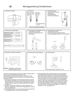
Toplock
D 1. Vorbereitung F Türflügel GB I Montageanleitung Schaltschloss 2. Befestigung Blechschraube ST 4,2 x 13mm DIN 7982 Schraube M5 x 12mm DIN 965 3. Schaltschlossachse senkrecht über Achse des Gewindelochs (Treibriegelschloss, Anti-Panik-Gegenkasten) Blindnietmutter M5 nicht im Lieferumfang enthalten 4. Ermittlung der Stangenlänge L Panikgegenkasten Vollblatt Panikgegenkasten Vollblatt mit Stangenantrieb IQ AUT Panikgegenkasten lang Panikgegenkasten lang mit Stangenantrieb IQ AUT L = X - 41 L = X - 604 Panikgegenkasten kurz Panikgegenkasten kurz mit Stangenantrieb IQ AUT L = X - 73 L = X - 636 5. Einschlagen des Gleitstopfens nur im „nichtmontierten“-Zustand. Gewinde am Stangenende nicht beschädigen! 6. Treibriegelstange eindrehen und Schaltschloss montieren. Bei der Montage der Treibriegelstangen muss das Anzugsdrehmoment … - … Nm betragen. 8. Ausrichtung des Schaltschlosses 9. Funktionsprobe L = X - 126 L = X - 672 3-6 mm 7. Bei großer Türluft Stulp unterfüttern Achtung: Schließblech im Bereich des Fallenaufschlages anfasen Zum Einbau des Schaltschlosses dürfen nur Artikel verwendet werden, welche in der Montageanleitung beschrieben sind. Die Anleitungen bzw. Anweisungen müssen vom Monteur an den Benutzer weitergegeben und von diesem bis zum Ende der Nutzung aufbewahrt werden. 1. Die Flügel und der Rahmen des Türelementes müssen aus ausreichend stabilen Werkstoffen (z.B. geschweißter Stahl oder Aluminiumprofil) bestehen. Die Verformung des Türelementes ist so gering zu halten, dass die Funktion der Verschlusselemente nicht beeinträchtigt wird. 2. Es dürfen nur Elemente erstellt werden, deren Flügelhöhe von 3000 mm, Flügelbreite von 1500 mm und Flügelgewicht von 300 kg nicht überschritten wird. 3. Das Verschlusssystem ist nach Feuerwiderstandsklasse EI60 (T60) in zweiflügeligen Stahl- und Aluminiumtüren geprüft. Bei Verklemmung, siehe Abb. … und … 4. Schlüsselbetätigte Halb- oder Doppelzylinder sowie mechanische oder elektronische Knaufzylinder, mit oder ohne Schlüsselbetätigung, haben keinen Einfluss auf die Paniktürfunktion des Schlosses (auch bei steckendem Schlüssel). Lediglich der Knauf eines mechanischen oder elektronischen Knaufzylinders kann in Abhängigkeit von der Knaufform und –größe die Funktion der Stangengriffe beeinflussen. Bei einigen Stangengriffen ist die Gefahr durch Quetschoder Scherstellen gegeben. Deshalb ist es wichtig, dass zwischen der Außenseite des Knaufs bis zum Hebelarm des Stangengriffs, oder eines anderen auslösenden Beschlagteils, ein Freiraum von mindestens 10 mm sichergestellt wird. D GB Installation instructions for switching lock F1. PreparationIof door leaf 2. Fixing self lapping screw screw ST 4,2 x 13mm M5 x 12mm DIN 7982 DIN 965 3. Align axle of switching lock perpendicularly above axle of tapped hole (espagnolette lock, panic keep) riv nut M5 not included 4. Determining the length (L) of the shoot bolt Panic keep full leaf Panic keep full leaf with rod drive IQ AUT Panic keep long Panic keep long with rod drive IQ AUT L = X - 41 L = X - 604 Panic keep short Panic keep short with rod drive IQ AUT L = X - 73 L = X - 636 5. Drive in sliding stopper only in unscrewed status. Do not damage the thread at the end of the bolt 6. Turn shoot bolt in and mount switching lock. During mounting the shoot bolts the locking torque has to be 5-8 Nm. 8. Align switching lock 9. Function test L = X - 126 L = X - 672 3-6 mm 7. Shim forend if there is more door clearance Attention: Chamfer striking plate where latch bolt hits Only use articles which are describe in these instructions. These instructions and directions should be passed to the end user by the installer and keep reliably up to the end of the working life. 1. The leaves and the frame of the door element must be made of sufficiently sturdy materials (e.g. welded steel or aluminum profile). Make sure that any deformation in the door element is kept to a minimum to ensure that the locking element will work properly. 2. The leaf dimensions in the door elements produced may not exceed 3000 mm in height, 1500 mm in width or 300 kg in weight. 3. The locking system complies with fire rating EI60 (T60) for double-leaf steel and aluminum doors. If jammed, see point … and … 4. Key-operated half- or double cylinders as well as mechanical or electronic knob cylinder (with or without key operation) have no effect on the lock’s panic door function (even when the key is inserted). Only the knob of a mechanical or electronic knob cylinder can affect the push bar’s functioning, depending on the knob shape and size. Some push bars pose the risk of pinch or shearing points. That’s why it’s important to keep a clearance of at least 10mm between the outside of the knob up to the lever arm or other activating fitting. Leaving technical details.
PDF | 634 KB